inquiry
Leave Your Message

How to Choose the Right Common Mode Choke?

Modern electronics operate in a noisier environment than many design teams expect. Electric vehicles, fast chargers, industrial drives, and compact data systems all increase switching activity. The International Energy Agency reported more than 14 million electric cars were sold worldwide in 2023. That growth brings more high-frequency current paths into smaller enclosures. A Common Mode Choke can reduce unwanted common-mode noise, but choosing one requires more than comparing inductance values.

This guide explains how to match a Common Mode Choke with the circuit, load, and compliance target. Engineers should examine impedance across the actual noise spectrum, not only the headline rating. Current capacity, saturation behavior, winding resistance, thermal rise, and insulation strength also matter. A part rated for 10 amps may perform poorly near its upper temperature limit. Check the datasheet carefully. Then test the assembled product.

CISPR 32 and related EMC requirements remind designers that emissions depend on the complete system. Cable length, grounding, connector placement, and PCB return paths can change results dramatically. The IEC 60938 series provides useful component and safety considerations for fixed inductors and filters. Industry reports from the IEA and Ericsson also show continuing growth in electrification and connected equipment. More devices mean more opportunities for interference. A perfect component choice on paper can still fail in the laboratory. That assumption deserves checking. Practical selection combines calculations, manufacturer curves, prototype measurements, and independent EMC testing. This article offers a clear path through those decisions, while recognizing that real hardware is often less predictable than simulations.
How to Choose the Right Common Mode Choke?

What Is a Common Mode Choke and How Does It Work?

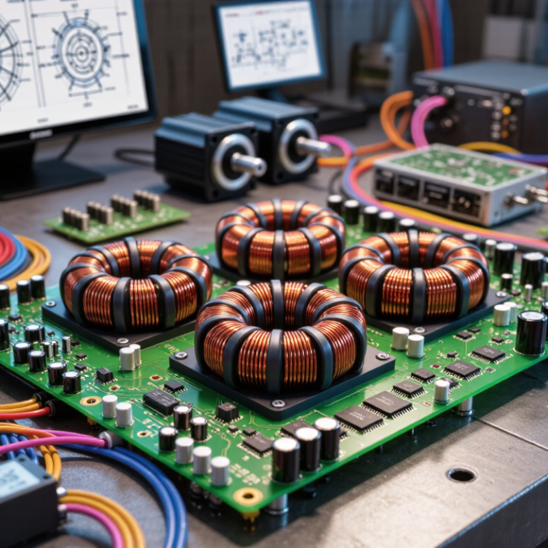
A common mode choke is a passive noise filter with two windings on one magnetic core. It targets unwanted signals shared by two conductors. Useful signals usually travel in opposite directions, while common-mode noise travels in the same direction.

The operating principle is simple. Common-mode currents create magnetic fields that reinforce each other. The core then presents high impedance to that noise. Differential currents create opposing fields, so their flux largely cancels.

At higher frequencies, parasitic capacitance can reduce this effect.

The IEC 60939-1 standard addresses passive filter performance, while CISPR 16-1-1 defines receiver methods from 9 kHz to 18 GHz. These ranges show why one impedance value cannot describe every application.

Choose the choke from measured noise, not only its headline impedance. Check impedance across the actual interference band, rated current, temperature rise, and saturation behavior. A component rated for 10 A may perform poorly near saturation.

Keep the layout compact, and place the choke near the cable entry. Bench testing remains essential. A neat schematic can still mislead.

In practice, the first choice is often wrong. Compare conducted-emission scans before and after installation, using the same cable length and load conditions. Otherwise, the measured improvement may belong to the test setup, not the choke.
Identify the Noise Suppression Requirements

Start by identifying the noise you need to suppress. A common mode choke targets currents that travel in the same direction on paired conductors. It will not automatically fix differential-mode noise, which flows in opposite directions. Measure the interference across the frequencies that matter to your equipment. A spectrum analyzer and suitable current probe can reveal peaks that a single reading might miss. Note when they occur, such as during switching or motor startup.

Then compare the measured noise with the limits or operating targets for your system. Check the choke’s impedance across the problem frequency range, not just at one frequency. Also verify rated current, temperature rise, winding resistance, and voltage requirements. A part with high impedance on paper may perform differently in your circuit because of parasitic capacitance and source or load conditions. Bench tests are useful, but installation layout can change the result.

Tips: Keep the cable pair together through the choke, and place it near the point where noise enters or leaves the circuit. Test under realistic loads. Measurements are not always tidy; if results shift between runs, check probe placement and cable routing before choosing a different part.

How to Choose the Right Common Mode Choke? — Identify the Noise Suppression Requirements

Set a target attenuation for each frequency range based on your system’s measured common-mode noise. The values below are illustrative design targets, not measured performance of a specific choke.

Compare these targets with the choke’s impedance-versus-frequency data and verify the result in your actual circuit. Performance depends on the source and load impedances, layout, and parasitic capacitance.

Select the Core Material and Choke Configuration

Core material should match the frequency range of the unwanted noise.

Ferrite is common in high-frequency circuits, but ferrite grades behave differently. Check impedance curves rather than choosing by material name alone. A choke that works well at 1 MHz may offer little suppression at 30 MHz.

Measure the noise under real operating conditions, if possible. Small details matter.

Nanocrystalline cores can provide high permeability across useful frequency ranges, while other materials may suit different size, cost, or temperature limits.

Compare the core’s specifications with the expected current and frequency.

In a balanced circuit, the wanted currents largely cancel their magnetic effects. Unequal currents can change that.

Don’t assume saturation is impossible.

Configuration matters too.

Closely coupled windings, such as bifilar windings, can reduce leakage inductance, but their added capacitance may weaken performance at higher frequencies. More widely spaced windings may reduce capacitance, though they can introduce other trade-offs.

Check winding direction and pin placement against the circuit diagram; a reversed connection can undermine the intended behavior.

Leave room for measurement. An impedance analyzer or a simple test setup can reveal dips that a datasheet plot may not show in your layout.

The first choice may not be the final one.

Match Electrical Ratings to the Application

How to Choose the Right Common Mode Choke?

Match Electrical Ratings to the Application

Choosing a common mode choke starts with the real electrical conditions, not only the advertised impedance. A choke must handle the circuit’s continuous RMS current without excessive heating. If the load draws 3.2 A, a 3 A rating is not an acceptable match. Small margins matter. Check peak current, inrush current, and the maximum ambient temperature. A cabinet reaching 55°C can reduce the available current capacity significantly. Measure the operating waveform when possible.

Voltage ratings require equal attention. Review the working voltage, insulation rating, and withstand voltage for the complete circuit. Mains applications also demand careful checks of creepage and clearance distances. Low-voltage systems still face switching spikes, especially near motors or long cables. A component may pass a short bench test and fail after repeated thermal cycling. That detail is easy to overlook.

Frequency behavior affects selection too. Confirm the impedance at the noise frequencies your equipment actually produces. A choke with excellent performance at 1 MHz may provide limited suppression at 100 kHz. Check saturation data and temperature-rise curves, not just one impedance value. Installation can change results. Wire size, winding direction, and the number of passes through the core all influence performance. A practical lesson is to test the finished assembly, because the ideal datasheet conditions rarely match the cabinet, cable length, and grounding arrangement.

Verify Performance, Safety, and Installation Requirements

How to Choose the Right Common Mode Choke?

Verify performance, safety, and installation requirements before selecting a common mode choke. Start with the actual interference problem, not only the rated current. Compare impedance across the frequency range where noise appears. A high impedance at 100 MHz may provide little benefit at 1 MHz. Check common mode attenuation separately from differential mode performance. A choke can reduce unwanted noise while still allowing normal power current to pass.

Confirm the rated current, voltage, insulation system, and temperature limits. Measure DC resistance and estimate heat rise under the worst operating load. A small package may fit the board but overheat during continuous operation. Review the applicable safety standards for creepage, clearance, dielectric strength, and insulation category. Do not treat a familiar symbol or certification mark as complete evidence. Request test conditions and verify whether they match your product.

Installation can change performance significantly. Keep noisy conductors together through the choke, and avoid routing them beside sensitive signal traces. Minimize copper loops on both sides. Follow the specified winding direction and pin arrangement. Check solder-joint quality and mechanical support during vibration testing. In bench testing, I would compare emissions before and after installation, then repeat the test inside the final enclosure. Results may differ. That difference deserves investigation, not a convenient explanation.

How to Choose the Right Common Mode Choke? — Verify Performance, Safety, and Installation Requirements
Selection Dimension What to Verify Example Requirement or Check Why It Matters
Noise frequency range Identify the frequencies where common-mode emissions or susceptibility are a concern. Review impedance-versus-frequency curves rather than relying on a single impedance value. For a switching converter operating near 100 kHz, assess conducted noise across the applicable measurement range, commonly extending from 150 kHz to 30 MHz for conducted-emissions testing. Choke impedance varies with frequency. A component that is effective in one band may provide limited attenuation in another.
Common-mode impedance Compare the choke’s common-mode impedance at the frequencies of interest. Check the measurement conditions and test method in the datasheet. Choose a curve that provides useful impedance in the observed noise band; confirm performance in the assembled circuit with suitable EMC testing. Impedance helps indicate filtering potential, but actual attenuation also depends on source and load impedances, layout, and parasitic coupling.
Rated current and temperature rise Check the rated current, allowable temperature rise, ambient-temperature conditions, and any required derating. For a 2 A continuous line current, select a part whose current rating and thermal performance meet the design conditions, with margin for operating temperature and enclosure heating. Excessive current can cause overheating and may reduce reliability. Current ratings are specified under particular thermal conditions.
Winding resistance and voltage drop Review the maximum DC resistance of each winding and estimate conduction loss at the expected current. Estimate winding loss using P = I²R for each current-carrying winding, then verify the resulting temperature rise in the intended operating environment. Higher winding resistance increases losses and can contribute to heating or unwanted voltage drop.
Differential-mode behavior Check leakage inductance, differential-mode impedance, and the effect of any capacitors used with the choke. Confirm that the filter does not create an undesirable resonance or interfere with the normal differential-mode current. A common-mode choke is intended primarily to impede common-mode noise; its non-ideal properties can also affect differential-mode behavior.
Core saturation and current imbalance Determine whether the device is suitable for the expected current balance, transient conditions, and any DC component that could affect the core. For paired supply and return conductors, verify that normal load currents flow in opposite directions through the windings and that the manufacturer’s limits are met. Imbalanced currents can reduce effective inductance or cause performance to differ from the expected common-mode behavior.
Rated voltage and insulation Verify the working voltage, insulation system, dielectric withstand rating, and creepage and clearance requirements for the application. For equipment connected to hazardous mains, use a component whose approvals and insulation ratings are appropriate for the applicable product and safety standards. Voltage and insulation suitability are safety-critical and cannot be inferred from inductance or current ratings alone.
Safety approvals and environment Check recognized approvals, operating-temperature range, humidity conditions, and any applicable pollution-degree or overvoltage requirements. Match the component documentation to the end product’s applicable standards and expected installation environment. Component approvals and environmental limits help support safe operation but do not replace evaluation of the finished equipment.
Package and installation Confirm footprint, pin spacing, mounting method, conductor size, soldering limits, and mechanical clearances. Keep noisy and quiet circuit regions appropriately separated, minimize unnecessary lead length, and follow the recommended land pattern and mounting orientation. Poor placement or excessive wiring can add parasitic coupling and reduce the practical filtering benefit.
Validation in the finished design Measure emissions or immunity using the relevant test setup and verify thermal performance under representative operating conditions. Test at expected line voltage, load, switching modes, cable configuration, and environmental conditions; compare results with the applicable limits. Datasheet values are measured under defined conditions. Final performance depends on the complete circuit, layout, cables, and enclosure.
Example checks are guidance, not universal design limits. Confirm all electrical, thermal, mechanical, and safety requirements against the component datasheet and the standards applicable to the finished product.