Leave Your Message
Common-mode noise can turn a reliable design into a stubborn troubleshooting exercise. A cable may radiate interference even when its signal looks clean on an oscilloscope. A Common Mode Choke helps by presenting impedance to unwanted common-mode currents while allowing differential signals to pass. The details matter: impedance across frequency, rated current, winding resistance, package size, and temperature rise all affect the result.
The market context is growing. Grand View Research valued the global electromagnetic interference shielding market at about $7.0 billion in 2022 and forecast continued growth through 2030. That figure covers shielding, not common-mode chokes alone, so it should not be mistaken for choke-market sales. Still, it reflects the broader pressure to manage electromagnetic interference in compact electronics. Henry W. Ott, an EMC specialist, captured the system-level challenge: “The most important thing to remember about noise is that it is a system problem.” His book, Electromagnetic Compatibility Engineering (Wiley, 2009), remains a useful reference for engineers.
This guide compares ten common-mode chokes for EMI filtering across practical selection factors, including impedance curves, current ratings, and mounting constraints. A large impedance number is not an automatic win. Check the relevant frequency band, then verify performance in the actual circuit and layout. Bench results can differ from the datasheet. Selection is rarely tidy. The best component is the one that reduces measured noise without creating unacceptable voltage drop, heat, or signal distortion. These comparisons offer a starting point, not a substitute for testing.
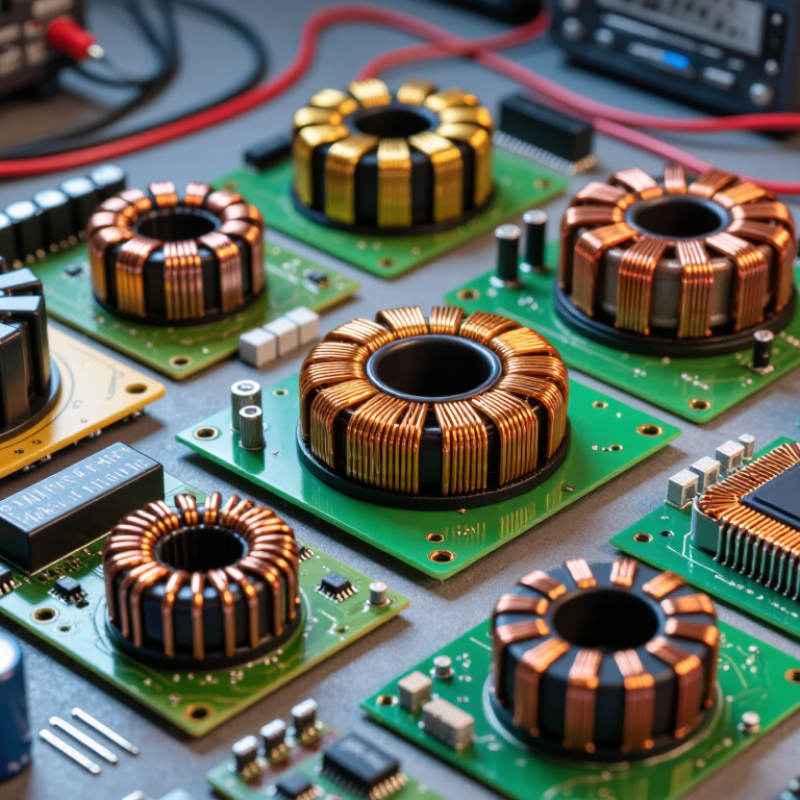
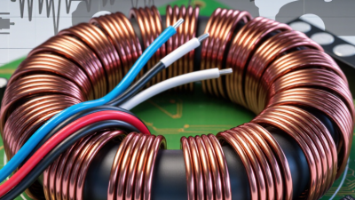
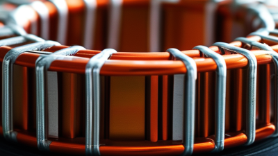
A common mode choke is a magnetic component that helps limit unwanted electrical noise on paired wires. Common mode noise travels in the same direction along both conductors, often escaping through cables and interfering with nearby circuits. Inside the choke, two windings share a magnetic core. Normal differential currents create opposing magnetic fields that largely cancel. Common mode currents reinforce the fields, so the choke presents greater impedance to that noise. It reduces interference without ideally disrupting the wanted signal. Not magic.
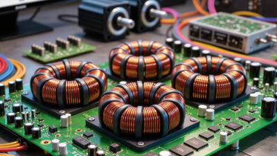
Tips: Place the choke near the cable entry point, where noise can enter or leave the enclosure. Check its current rating, impedance across the frequencies of concern, and temperature limits. Keep connections short and layout tidy; stray capacitance can weaken filtering at high frequencies. Measure noise before and after installation when possible.
A choke works best as part of a considered filter, not as a stand-alone fix. Long traces, poor grounding, or noise from another source may still cause problems. A component that looks suitable on paper can behave differently in a real circuit. That is easy to overlook. Test the finished design under its actual operating conditions, and be ready to adjust the filter.
Common-mode chokes impede noise currents flowing in the same direction on multiple conductors while allowing the intended differential signals or power current to pass. The entries below compare common application types, not specific products or a universal performance ranking; actual ratings and impedance must be verified in the component datasheet and the finished design.
| No. | Choke type | Typical application | Key selection data to verify | Practical EMI-filtering considerations |
|---|---|---|---|---|
| 1 | AC mains input choke | Single-phase equipment power inputs | Rated current, winding resistance, common-mode impedance versus frequency, insulation and safety approvals, temperature rise, and leakage-current implications. | Often used with capacitors in an input filter. Check that the complete filter meets applicable safety and conducted-emissions requirements. |
| 2 | Three-phase power-line choke | Industrial drives, converters, and three-phase equipment | Number of phases and conductors, continuous and overload current, insulation rating, core temperature, winding resistance, and impedance across the relevant noise spectrum. | All phase conductors are commonly routed through the core together. The protective-earth conductor is not treated as a phase winding. |
| 3 | DC input choke | DC power supplies, battery-powered equipment, and converter inputs | DC current rating, resistance and resulting voltage drop, operating temperature, common-mode impedance, insulation, and behavior under the expected DC bias. | Check both conducted-noise performance and power loss. A choke that is suitable for signal lines may not have adequate current or thermal capacity for a power rail. |
| 4 | Ethernet line choke | Twisted-pair Ethernet ports and transformer-coupled interfaces | Supported Ethernet data rate, insertion loss, return loss, winding balance, common-mode rejection, isolation requirements, and compatibility with the interface layout. | Preserve pair symmetry and controlled routing. The choke must suppress common-mode noise without materially degrading the differential signal. |
| 5 | USB data-line choke | USB ports and high-speed differential data lines | Supported signaling rate, differential insertion loss, return loss, common-mode attenuation, line capacitance, and connector-side placement requirements. | Choose a part intended for the specific signaling class. Excessive parasitic capacitance or poor layout can impair signal integrity. |
| 6 | CAN-bus choke | CAN and CAN FD transceiver interfaces | Bus data rate, differential signal integrity, common-mode impedance, line balance, temperature range, and the transceiver and network requirements. | Place the choke close to the interface when appropriate, and validate the complete bus for waveform quality and communication errors. |
| 7 | RS-485 / RS-422 line choke | Differential serial links and industrial communication ports | Signaling rate, differential insertion loss, common-mode range of the transceiver, line balance, impedance versus frequency, and environmental rating. | Use a choke designed for differential signaling. Confirm that it does not compromise signal edges or the required common-mode operating range. |
| 8 | HDMI / high-speed video line choke | High-speed video and display interfaces | Supported data rate, insertion and return loss, channel balance, parasitic capacitance, and compatibility with the interface’s signal-integrity requirements. | High-speed channels are sensitive to added parasitics. Evaluate the choke as part of the complete channel, including connectors, traces, and cables. |
| 9 | Common-mode choke for switching-converter inputs or outputs | Switch-mode power supplies and DC-DC converter connections | Current rating, winding resistance, saturation and temperature behavior, impedance over the switching-noise spectrum, and interaction with other filter components. | Measure noise on the assembled circuit. Filter resonance and PCB layout can affect results, so component selection alone does not guarantee compliance. |
| 10 | Ferrite sleeve or cable common-mode choke | External cables, harnesses, and retrofit EMI suppression | Ferrite material and impedance-frequency curve, cable diameter, number of turns, temperature limits, and mechanical fit. | A sleeve around the complete cable primarily targets common-mode current. Its effectiveness depends on the ferrite material, frequency, cable routing, and installation position. |