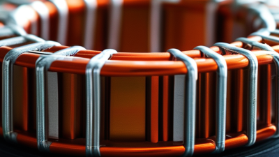
A Common Mode Choke is a quiet component with a demanding job. It suppresses unwanted common-mode noise while allowing useful differential signals to pass. You may find it near a power inlet, USB port, motor drive, or communication interface. Its paired windings share a magnetic core. Normal currents create opposing magnetic fields, so their effects largely cancel. Common-mode currents reinforce those fields, producing impedance and reducing interference.
This matters because modern devices operate faster, closer together, and with smaller voltage margins. Grand View Research’s EMI Shielding Market Analysis, 2024–2030, identifies automotive electronics, telecommunications, and consumer devices as major demand areas. MarketsandMarkets’ Electromagnetic Compatibility Market research also highlights rising compliance requirements across connected equipment. These trends increase the need for practical noise-control methods, not decorative component selection.
EMC engineer Henry W. Ott wrote, “The best way to solve an EMC problem is to avoid creating it in the first place.” His principle explains why engineers place a Common Mode Choke near the noise source or cable entry. Correct impedance, saturation current, leakage inductance, and frequency range still matter. A larger part is not automatically better. Real circuit boards are less tidy than diagrams suggest. Cable length, grounding, layout, and switching edges can change results. This introduction examines how the device works, where it performs best, and why laboratory data must be checked against actual operating conditions. Some explanations simplify the physics too much. That weakness deserves attention.
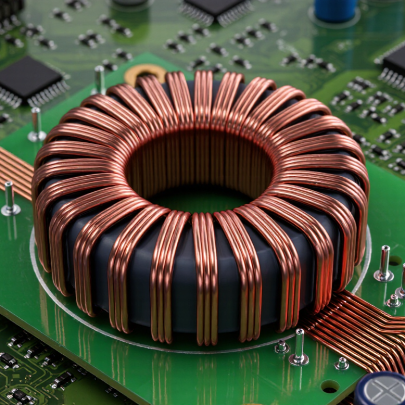
A common mode choke is a passive electromagnetic interference filter. It contains two or more insulated windings on one magnetic core. The windings carry supply and return currents together. During normal differential operation, their magnetic fields largely cancel. Common noise travels in the same direction through both conductors. Its magnetic fields then reinforce each other, creating high impedance against that unwanted current.
In practical equipment, this component may sit near a power connector, motor drive, or communication port. It helps reduce conducted noise before cables behave like unintended antennas. A 2024 EMI Shielding Market report from MarketsandMarkets projects growth from roughly 7 billion US dollars in 2024 to more than 10 billion by 2029. That expansion reflects stricter electromagnetic compatibility demands across electronics. However, market growth does not prove that every choke suits every circuit.
Selection needs measured details. Check impedance across frequency, rated current, saturation behavior, leakage inductance, insulation, and temperature rise. A choke that performs well at 150 kilohertz may weaken near 30 megahertz. Layout also matters. Short traces and close placement usually improve filtering. Real hardware is less predictable than a datasheet suggests. That assumption deserves testing. Oscilloscope measurements, conducted-emissions scans, and prototype testing reveal problems early. The IEC 60939-3 standard provides useful requirements for passive filter components, but engineers still need application-specific verification.
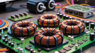
A common mode choke is a passive filter built around a shared magnetic core. It usually contains two insulated windings, one for each conductor in a power or signal pair. The useful signal travels through both wires in opposite directions. Their magnetic fields largely cancel inside the core, so the choke adds little impedance to normal operation.
Noise behaves differently. Common-mode noise moves in the same direction along both conductors, often returning through ground or stray capacitance. The two winding fields then reinforce each other. The core develops stronger magnetic flux and resists this unwanted current with higher impedance. That is the essential separation mechanism: differential signals see cancellation, while common-mode noise sees reinforcement.
The core material, winding balance, and frequency range determine the result. On a test bench, a properly selected choke can reduce radiated interference without noticeably weakening a data waveform. However, real components are not perfect. Leakage inductance can affect differential signals, and parasitic capacitance may provide a path for very high-frequency noise. A heavily loaded choke can also approach saturation, especially when direct current is present. Small wiring changes matter. I have seen a short, poorly arranged return path reduce the expected filtering effect. So the magnetic structure helps, but layout and measurement still decide whether the design works.
A common mode choke suppresses unwanted noise traveling together on multiple conductors. It uses two or more windings around one magnetic core. Normal load currents usually flow in opposite directions. Their magnetic fields then cancel each other. Common mode noise flows in the same direction. Its magnetic fields reinforce each other and create a strong opposing impedance.
This action makes high-frequency noise harder to pass. The choke does not significantly disturb the intended power or signal current. For example, a motor cable may carry useful current in opposite directions. Noise can ride along both wires toward the equipment frame or nearby circuits. The choke resists this shared noise before it spreads through the system.
Placement matters greatly. Install the choke near the noise source or the vulnerable input. Keep noisy and clean cable paths separated. Engineers often check insertion loss with network measurements, then verify performance inside the finished enclosure. A choke alone may not solve every problem. Parasitic capacitance can provide another path around it. Core material, winding balance, current rating, and frequency range also change results. The design may look correct on paper, yet fail during testing. That is a useful warning. Real cables, connectors, and grounding structures often behave differently from simplified models. Careful measurements reveal those hidden paths.
| Data Dimension | Technical Information | Practical Meaning |
|---|---|---|
| Component Definition | A common mode choke is a coupled inductor with two or more windings placed on the same magnetic core. | It is designed primarily to attenuate unwanted common-mode electromagnetic interference while allowing the intended power or signal current to pass. |
| Conductors or Windings | A two-line device normally has one winding for each conductor. The windings have similar inductance and are magnetically coupled. | Matching the windings improves common-mode rejection and reduces unwanted imbalance between the conductors. |
| Common-Mode Current Path | Common-mode current flows in the same direction on all conductors relative to chassis, earth, or another reference. | The magnetic flux produced by the windings adds together, creating high impedance to the unwanted noise current. |
| Differential-Mode Current Path | Differential current flows in opposite directions on paired conductors, such as line and neutral or positive and negative. | The magnetic flux largely cancels, so the choke presents much lower impedance to the desired load current than to common-mode noise. |
| Basic Suppression Principle | For an inductor, impedance increases with frequency according to ZL = 2πfL, where f is frequency and L is inductance. | Higher-frequency common-mode noise encounters greater impedance and is attenuated before it reaches the cable, source, or load. |
| Typical Noise-Frequency Range | Common-mode interference is frequently addressed from approximately 100 kHz to 300 MHz, depending on the component, circuit, and test setup. | The usable suppression band is limited by winding capacitance, core behavior, layout, and parasitic resonances. |
| Typical Common-Mode Inductance | Representative values range from approximately 10 µH to 100 mH across power, signal, and data-interface applications. | Higher inductance generally provides stronger low-frequency filtering, but may increase size, parasitic capacitance, and conducted-current limitations. |
| Rated Current | Available current ratings commonly range from tens of milliamperes for signal circuits to several amperes for power-input filters. | The selected rating must account for continuous current, temperature rise, wire size, and the allowable reduction in inductance. |
| Core Materials | Common core materials include ferrite for high-frequency suppression and powdered iron or other magnetic materials for selected lower-frequency and power applications. | Core permeability, loss characteristics, saturation behavior, and frequency response determine the effective filtering performance. |
| Insertion Loss | A properly selected choke can provide several decibels to more than 30 dB of common-mode attenuation over part of its operating band; actual performance is circuit-dependent. | Attenuation depends on source and load impedance, frequency, parasitic capacitance, winding balance, PCB layout, and the presence of additional capacitors. |
| Differential-Mode Impact | An ideal common-mode choke has nearly zero differential-mode inductance because the opposing flux cancels. | Real devices still have leakage inductance, which can provide some differential-mode filtering but may also affect signal integrity or power losses. |
| Voltage Rating | The insulation system must withstand the specified working voltage, transient voltage, and required isolation test voltage. | Voltage rating is especially important in mains-connected equipment, where insulation distance and safety requirements apply. |
| Temperature Considerations | Copper loss increases temperature, while elevated temperature can reduce core performance and allowable current. | The choke should be evaluated using its temperature-rise specification, ambient temperature, airflow, and worst-case load current. |
| Typical Applications | Applications include AC and DC power inputs, switching power supplies, motor drives, industrial control wiring, communication interfaces, and USB or network cable assemblies. | The choke is placed where common-mode noise enters or leaves the equipment, often close to a connector or power-input boundary. |
| Filter Components Used With It | Safety-rated capacitors connected from line to line or from conductors to chassis are often used with a common-mode choke. | The choke provides series impedance, while capacitors provide a controlled return path for high-frequency noise. |
| Main Design Limitation | Performance decreases when the core saturates, windings are poorly balanced, parasitic capacitance dominates, or the component is installed with excessive high-frequency loop area. | Component selection must be verified with conducted- and radiated-emissions measurements in the final mechanical and electrical design. |
A common mode choke reduces electromagnetic interference on power or signal lines. It contains two windings on one magnetic core. Desired currents usually flow in opposite directions, so their magnetic fields largely cancel. Common mode noise flows in the same direction, causing the fields to add and create high impedance. Noise is blocked while the intended signal continues.
Selection starts with rated current. Check continuous current, peak current, and the acceptable temperature rise. A choke rated for average current may still saturate during startup. That mistake is easy to make. Inductance matters, but common mode impedance across the actual noise frequency matters more. Review the impedance curve rather than one headline value. Differential mode leakage inductance can also affect signal quality and power behavior.
Voltage rating, insulation strength, creepage, clearance, and dielectric testing require careful attention. Direct-current resistance indicates heat loss and voltage drop. In a practical circuit, compare the choke’s thermal performance with the enclosure temperature, not only room-temperature data. Measure conducted noise with the intended cable length and grounding arrangement. A different cable can change the result. A first selection is rarely perfect. That is normal. Leave reasonable electrical and thermal margin, then test under maximum load, startup conditions, and nearby switching activity.
What Is a Common Mode Choke and How Does It Work?
Typical Applications and Practical Design Considerations
A common mode choke reduces unwanted noise on cables and power lines. It uses two or more windings around one magnetic core. Normal current flows in opposite directions, so the magnetic effects largely cancel. Common mode noise flows in the same direction and strengthens the magnetic field. The choke then presents higher impedance to that noise. This principle sounds simple, but real circuits are less predictable.
Common applications include AC input filters, DC power cables, motor drives, USB interfaces, and audio equipment. Engineers often install the choke near the cable entry point. This location limits the distance that noisy current can travel. Select a part with enough continuous current capacity and suitable insulation ratings. Check its impedance at the actual noise frequency, not only at a preferred test frequency. A choke may perform well in testing but poorly inside a crowded enclosure.
Tips: Keep the noisy and clean sides physically separated. Minimize loop areas around the choke. Check differential-mode effects, because winding imbalance can create unwanted voltage drop. Watch for core saturation during startup or overload conditions. Measure conducted emissions before and after installation. Do not rely on the component alone; grounding, shielding, and PCB layout also matter. In practice, designers sometimes choose a larger choke too quickly. That can increase cost, leakage capacitance, and installation space without solving the real noise path. Review the complete current route. Test again.
A common mode choke presents a high impedance to currents flowing in the same direction on multiple conductors, while ideally allowing equal and opposite differential currents to pass. This calculated example uses a 10 mH common-mode inductance and the ideal relationship Z = 2πfL. Real components show lower impedance near and above their self-resonant frequency because of winding capacitance and core losses.
Typical applications include AC power input filtering, switching power supplies, motor drives, USB and Ethernet interfaces, and DC power lines. Practical selection should consider rated current, saturation, winding resistance, leakage inductance, safety spacing, temperature rise, and the expected noise-frequency range.