inquiry
Leave Your Message

How to Choose the Right Transformer Core for Global Sourcing?

Choosing the right Transformer Core for global sourcing is a technical decision, not merely a purchasing exercise. Core material, shape, size, loss level, supplier capability, and regional logistics all affect the final result. A core that performs well in a laboratory may create problems during mass production. Small differences in lamination thickness can change noise, heat, and efficiency.

Dr. S. V. Kulkarni, a respected transformer engineering author, emphasizes, “Core material and geometry must be selected together, not separately.” This principle remains useful when comparing silicon steel, ferrite, amorphous metal, and nanocrystalline options. Each material responds differently to frequency, flux density, temperature, and operating conditions. The correct Transformer Core must match the intended voltage, power range, switching frequency, and insulation design.

Look closely at the details.

A reliable sourcing process should examine certified material data, dimensional tolerances, joint quality, coating consistency, and traceability. Ask suppliers for test records, sample measurements, and production references. A polished datasheet is not enough. The factory floor tells more.

Cost can also mislead. A cheaper core may increase winding size, cooling requirements, or rejection rates. I have seen buyers focus on unit price while overlooking transport damage and inconsistent stacking. That approach deserves reconsideration. Global sourcing adds currency changes, lead-time uncertainty, communication gaps, and local compliance requirements. This article introduces a practical framework for evaluating suppliers, comparing core technologies, and balancing performance with supply-chain resilience. There is no universal best choice. Only the most suitable one.

How to Choose the Right Transformer Core for Global Sourcing?

Define Voltage, Power, and Frequency Before Choosing the Core

Choosing a transformer core starts with electrical facts, not a catalog photograph. Write the primary voltage, secondary voltage, rated power, and operating frequency on one sheet. For example, a 230-volt input, 12-volt output, and 60-watt load require different decisions than a 115-volt, 10-watt circuit. Include voltage tolerance, too. A nominal value may hide brownouts, surges, or a continuous load above its label. Frequency matters because a design approved only at 60 hertz can overheat at 50 hertz. Do not guess.

Power determines core size, copper area, and expected temperature rise. For a 60-watt transformer, I normally allow practical headroom instead of matching 60 watts exactly. A 20 percent margin is a starting point, not a universal rule. Check inrush current, duty cycle, insulation class, and cooling conditions before freezing the specification. The winding window must fit the wire and insulation without forced packing. Tight packing looks efficient, but it can make production inconsistent. Ask the supplier for loss data, saturation limits, drawings, and test conditions.

Global factories may quote the same core size with different steel grades or tolerances. Confirm the material standard and verify samples at the actual voltage, frequency, and load. Measure no-load current, temperature after several hours, and output voltage under load. I once trusted a calculated core area and underestimated heat from a cramped winding. The prototype passed briefly, yet failed the longer test. That mistake changed my process. Electrical inputs must be defined before mechanical selection. Leave room for uncertainty.
Compare Materials: Silicon Steel 1.5–1.7 T, Ferrite 0.3–0.5 T

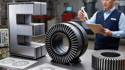
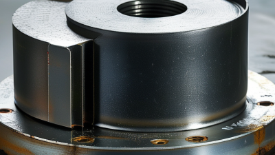
Choosing the right transformer core begins with its working frequency, power level, and thermal environment. Silicon steel typically supports 1.5–1.7 T, making it suitable for mains-frequency transformers and higher power density. Its laminated structure reduces eddy-current losses at 50 or 60 Hz. However, poor insulation between laminations can increase heat and noise.

Ferrite usually operates around 0.3–0.5 T. It suits high-frequency transformers because its electrical resistance is much higher. Ferrite cores can reduce switching losses in compact power supplies. Yet, the lower flux density requires more turns or a larger magnetic path. That affects copper cost and winding space. I once compared cores only by saturation figures. That was not enough. Temperature changed the result.

Tips: Request complete material data, including core loss curves, permeability, tolerance, and testing temperature. Check the supplier’s sample measurements, not only catalog values. Confirm dimensions, packing protection, and production consistency before global shipment. A small air gap can be useful in some designs, but it also changes inductance and energy storage. Ask for a controlled prototype test at the intended frequency and temperature. Some ferrite grades perform poorly outside their tested range. Silicon steel may appear stronger, but its weight and shipping volume can increase landed cost. Keep a documented comparison covering efficiency, noise, thermal rise, availability, and inspection results.

Match Core Type to Frequency: Steel at 50/60 Hz, Ferrite Above 20 kHz

How to Choose the Right Transformer Core for Global Sourcing?

Frequency should guide your core decision before price or availability. For 50/60 Hz power transformers, laminated electrical steel remains the practical choice. Its high saturation capability supports large magnetic flux at low frequency. Core size, stacking factor, and lamination thickness directly affect heat and efficiency. A poorly clamped core may also create an audible hum.

Ferrite is usually better above 20 kHz. Its high electrical resistance reduces eddy-current loss during fast switching. This makes ferrite suitable for compact converters, adapters, and high-frequency isolation transformers. However, ferrite saturates more easily than steel. Check the material’s operating temperature, permeability, and loss curve at the real switching frequency. Never rely on a catalog value alone.

Tips: Ask suppliers for tested core-loss data, dimensional drawings, and samples from the intended production lot. Confirm the bobbin fit and winding window with your actual wire. Small gaps matter. I have seen designs pass calculations but fail after assembly because the core temperature rose unexpectedly. Do not treat 20 kHz as a universal boundary; some designs need specialized materials near that range. Review waveform, duty cycle, ambient temperature, and cooling conditions together. A lower-cost core can become expensive when excessive heat requires redesign.

Size the Core with Ae, Aw, and Bmax Under IEC 61558 Safety Rules

Choosing the right transformer core starts with three numbers: Ae, Aw, and Bmax. Ae is the effective magnetic cross-sectional area. It determines how much flux the core can carry. Aw is the usable window area for copper, insulation, and bobbin structure. Bmax is the permitted peak flux density at the expected temperature.

For a first estimate, use the transformer equation: Np ≥ Vin ÷ (4 × f × Bmax × Ae) for a square-wave design. Sine-wave designs require a different waveform factor. Keep operating flux below the material’s practical limit, not merely its room-temperature headline value. A lower Bmax can reduce saturation risk and audible noise. It may also require more turns and a larger window. That trade-off matters.

Safety changes the geometry. Under IEC 61558, reinforced insulation, creepage, clearance, dielectric strength, and thermal performance must be checked together. Do not treat Aw as copper space alone. Insulation barriers can consume valuable winding area. Core shape, bobbin dimensions, winding method, and tolerances affect production yield. A useful sourcing request should include Ae and Aw definitions, Bmax conditions, material data, temperature ratings, and test evidence.

A neat calculation can still mislead. I have seen designs pass the spreadsheet and fail after winding. Recheck hot resistance, peak voltage, assembly variation, and abnormal operation. Leave sensible margin. Then compare samples from more than one approved source before committing to volume.

How to Choose the Right Transformer Core for Global Sourcing?

Core sizing uses effective magnetic cross-sectional area (Ae), window area (Aw), and the selected maximum flux density (Bmax). A larger Ae·Aw product generally supports higher power while limiting flux density and winding congestion.

The plotted values are calculated engineering design examples using Ae and Aw in cm² and Bmax in tesla. The area-product values are 3.0, 8.0, 20.8, and 50.0 cm⁴. Under IEC 61558, magnetic sizing is only one part of compliance; protective separation, insulation coordination, creepage and clearance distances, dielectric strength, temperature rise, and construction must be verified for the selected working voltage and insulation system.

Verify Global Suppliers Against IEC, UL, RoHS, MOQ, and Lead-Time Data

Choosing a transformer core for global sourcing requires more than comparing magnetic properties. Supplier verification must connect technical data with compliance, quantity, and delivery reality.

Request the exact IEC test reports, not a general compliance statement. Check the core material, insulation system, temperature class, and applicable test dates. UL documentation should match the finished component, not only a raw material certificate. RoHS evidence must identify restricted substances and supporting laboratory methods. I once reviewed a promising supplier whose RoHS file covered resin, but not the coating. That gap mattered.

Ask for traceable samples from the same production line. Measure dimensions, surface finish, lamination thickness, and loss values against the datasheet. A small dimensional difference can affect winding space and assembly noise. Review the supplier’s MOQ by core size, grade, and packaging unit. A low quoted price may hide an impractical 2,000-piece minimum. Lead-time data also needs detail: sample approval, tooling, production, inspection, and ocean or air transport. Request recent delivery records, then compare promised dates with actual receipts. Allow buffer time. Real schedules move.

Keep a verification sheet for every supplier. Record document numbers, revision dates, sample results, MOQ, payment terms, and shipment history. Do not treat a polished spreadsheet as proof. Factory capacity, inspection discipline, and communication quality often decide whether the selected core performs consistently. Some assumptions will remain uncertain, especially when suppliers provide incomplete loss curves or changing material codes. Flag them, test them, and revisit the decision before releasing a purchase order.