How to Choose the Right Transformer Core?
Choosing the right Transformer Core affects efficiency, temperature rise, noise, and long-term reliability. A suitable core must match the transformer’s power rating, operating frequency, voltage, and physical limits. It also influences winding design, insulation requirements, and manufacturing cost. Small design errors can create noticeable losses.
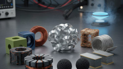
Experienced engineers usually compare silicon steel, ferrite, powdered iron, and nanocrystalline materials. Each option behaves differently under frequency, flux density, and temperature changes. Ferrite often suits high-frequency applications, while laminated steel remains practical for many power-frequency transformers. Nanocrystalline cores can deliver excellent magnetic performance, but their cost and availability require careful evaluation. Material datasheets provide useful guidance, yet real operating conditions matter more than attractive laboratory figures.
Details matter.
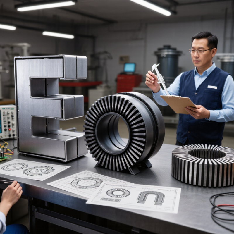
Core shape also deserves attention. E-cores, toroidal cores, and U-cores offer different advantages for assembly, leakage control, heat removal, and winding space. During development, engineers should verify core loss with realistic waveforms, not only with ideal sine waves. They should also inspect clamping pressure, air gaps, audible vibration, and temperature at full load. These checks support dependable decisions and reflect professional engineering practice.
No selection method is flawless. A core that performs well in a prototype may disappoint after production tolerances, damaged surfaces, or uneven winding tension appear. I have seen specifications treated as final answers when they were only starting points. Therefore, this guide focuses on practical comparison, measurable performance, and informed judgment. The best Transformer Core is not simply the smallest or cheapest option. It is the one that performs safely, consistently, and economically within its actual working environment.
Define the Core’s Job: 50/60 Hz Power or High-Frequency Switching
How to Choose the Right Transformer Core?
Define the core’s job before choosing its material. A 50/60 Hz power transformer needs low hysteresis loss, stable flux, and strong insulation. Grain-oriented electrical steel remains practical for larger line-frequency units. The U.S. Department of Energy’s 2024 distribution-transformer rule projects significant lifetime energy savings, showing why core loss matters beyond the purchase price. A core that runs cool may also reduce enclosure size and maintenance pressure.
High-frequency switching transformers face a different problem. Ferrite cores usually suit tens or hundreds of kilohertz because they limit eddy-current loss. However, higher frequency does not automatically mean better efficiency. Copper skin effect, leakage inductance, winding layout, and heat removal can dominate the result. The International Energy Agency’s Electricity 2024 report expects data-centre electricity demand to exceed 1,000 TWh by 2026. That growth increases pressure for compact, efficient conversion hardware. Still, I sometimes see designs chase smaller cores too early. The magnetic waveform deserves attention first.
Tips: Confirm frequency, duty cycle, peak flux density, temperature, and required isolation. Compare core-loss curves at the actual operating temperature. Leave margin for waveform distortion. A spreadsheet estimate is useful, but a thermal test may expose the uncomfortable truth.
Compare Core Materials by Data: Ferrite 0.3–0.5 T vs Steel 1.8–2.0 T
How to Choose the Right Transformer Core?
The core material sets the transformer’s working limits. In practical design work, ferrite commonly uses about 0.3–0.5 T as a reference range. Laminated electrical steel can approach 1.8–2.0 T before saturation becomes critical. These values are approximate, not universal ratings. Frequency, temperature, waveform, and air gaps can change the safe operating point. A higher flux density does not automatically create a better transformer.
Ferrite performs well in high-frequency converters because it has low eddy-current loss. Its lower saturation limit requires careful control of volt-seconds and temperature. Electrical steel suits power-frequency transformers, especially at 50 or 60 Hz. Its higher flux density supports a smaller magnetic cross-section. However, steel becomes inefficient at high frequency and may add considerable weight. It feels robust. It is not always efficient.
I once compared cores using saturation data alone. That shortcut was wrong. For a 100 kHz design, I would examine core-loss curves, winding space, cooling, and the actual switching waveform. For a mains transformer, I would check lamination thickness, magnetizing current, and temperature rise. A ferrite core near 0.5 T may suffer sharp heating, even when calculations appear acceptable. Steel near 2.0 T also needs caution, since manufacturing tolerances and voltage distortion can reduce the margin. Testing the assembled transformer remains essential.
Ferrite cores typically operate at lower peak flux density, around 0.3–0.5 T, but are well suited to high-frequency transformers because of their low eddy-current loss. Electrical steel cores can support approximately 1.8–2.0 T, enabling higher power density at lower frequencies, although core loss increases significantly as frequency rises. Actual limits depend on material grade, temperature, waveform, and operating frequency.
Match Core Geometry to Power: EI, UI, Toroidal, C, and E Cores
How to Choose the Right Transformer Core?
Core geometry should follow power, frequency, heat, and production limits.
EI cores suit low-to-medium power supplies because their laminations are affordable and easy to assemble.
E cores offer flexible bobbin designs and practical winding space.
UI cores support larger magnetic paths and high-voltage insulation, but their assembly can be less convenient.
Toroidal cores provide short magnetic paths, low leakage, and reduced audible hum. They often require slower, more specialized winding.
C cores can deliver low loss and compact construction, especially in higher-power equipment, although their material and assembly costs may rise.
The U.S. Department of Energy’s 2016 Technical Support Document estimated that distribution transformers consumed about
61 billion kWh annually in the United States.
That figure makes core loss more than a laboratory detail. No-load loss matters when equipment stays energized. Load loss matters during heavy operation. In practice, I measure temperature rise and magnetizing current before trusting a spreadsheet. Small gaps, poor clamping, or uneven stacking can change the result. The “best” core is rarely perfect.
Tips:
Start with VA, not physical size. Compare EI, UI, toroidal, C, and E cores at the same flux density. Check window area for copper clearance. Review the manufacturer’s loss curves and applicable IEC 60076 or IEC 61558 requirements. Leave thermal margin. A cheaper core can become expensive after years of wasted energy.
Check Loss and Temperature: Evaluate Core Loss at the Rated Frequency
Choosing the right transformer core starts with measured loss, not the lowest catalog price. At rated frequency, apply the intended volts per turn and waveform. Core loss then reflects hysteresis and eddy-current behavior under real excitation. A small test mistake matters.
IEC 60404-2 defines Epstein-frame methods for magnetic materials and controlled test conditions. Use its framework, or request equivalent ring-core data. Record frequency, peak flux density, waveform, and specimen temperature. Do not accept “low loss” without these details. The U.S. Department of Energy’s Distribution Transformer Technical Support Document (2013) evaluates no-load and load losses over 8,760 operating hours. That distinction is practical: core loss continues whenever the transformer is energized.
Temperature deserves careful attention. Magnetic behavior changes as the core warms, although the effect differs from copper resistance changes. Test near the intended operating temperature, then apply only a documented correction method. IEEE C57.12.90 provides recognized procedures for transformer-loss and temperature measurements. A 50 Hz core may not match a 60 Hz design. Neither will a clean sine-wave result fully predict inverter harmonics. The uncomfortable part is this: a neat datasheet can still hide test uncertainty, sampling limits, or an unrealistic waveform. Ask for loss tolerance and production-test evidence. Compare watts at rated frequency and flux, not efficiency alone.
Verify Flux Density, Window Area, and Safety Margins Before Selection
How to Choose the Right Transformer Core?
Verify Flux Density, Window Area, and Safety Margins Before Selection
Selecting a transformer core begins with flux density, not the catalog size. Calculate the expected peak flux from voltage, frequency, turns, and effective core area. Keep the working level below the material’s saturation limit. A small calculation error can create excessive magnetizing current, heat, and audible noise. Check core-loss data at the real operating temperature, because performance often changes after the core warms.
Window area deserves equal attention. The opening must accommodate copper, insulation, tape, and practical spacing. Do not fill the window completely. A crowded winding may pass an initial test but fail during production or thermal cycling. I once underestimated insulation thickness and had to revise the winding layout late. That mistake was avoidable. Review creepage, clearance, temperature rise, and mechanical support with qualified engineers before approval.
Tips: Measure the actual winding space. Use worst-case input voltage and lowest frequency. Add a sensible thermal margin. Compare calculated flux with test results. Inspect the first sample for hot spots, loose windings, and unexpected vibration. Leave room for manufacturing variation. Perfect assumptions rarely survive the workshop.