What Is a Common Mode Choke and How Does It Work?
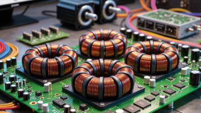
A Common Mode Choke is a passive component designed to reduce unwanted common-mode noise on electrical conductors. It uses coupled windings on a shared magnetic core. Desired current flowing in opposite directions largely cancels its magnetic effect, while common-mode interference produces fields that the core can oppose. The idea is compact. The practical behavior is less simple.
The need for careful noise control is growing with modern electronics. The International Energy Agency’s Global EV Outlook 2024 reports nearly 14 million electric car sales worldwide in 2023, about 18% of all car sales. Power converters in vehicles and chargers can generate electrical noise, making electromagnetic compatibility an important design concern. IEC 61000-4-6 describes conducted radio-frequency immunity testing, while CISPR 32 sets emissions requirements for multimedia equipment. These standards help engineers assess system performance; they do not guarantee that one component will solve every interference problem.
This article explains how a Common Mode Choke works, where it is used, and what its specifications mean. We will look at impedance, winding configuration, frequency response, and the effects of layout and parasitic capacitance. A choke may reduce noise on a cable, yet still leave differential-mode noise untouched. Not magic. Selecting one requires checking the actual frequency range, current rating, and circuit conditions—not just the largest impedance figure on a datasheet.
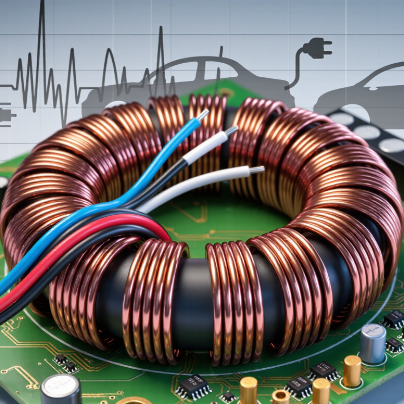
Definition and EMI-Filtering Role of a Common-Mode Choke
A common-mode choke is a passive component with two windings on one magnetic core. It targets unwanted noise that travels in the same direction on both conductors, such as live and neutral. For that noise, the magnetic fields reinforce each other, creating impedance that resists the current. Normal differential current produces opposing fields, so it can pass with comparatively little interference. That is the basic idea.
Its role is EMI filtering, especially where a power or signal cable enters equipment. A choke can reduce common-mode noise that would otherwise leave the enclosure or enter sensitive circuits. CISPR 32:2015 sets conducted-emission limits for multimedia equipment: for Class B mains ports, quasi-peak limits range from 66 to 56 dBµV between 150 and 500 kHz, then are 56 dBµV from 500 kHz to 5 MHz. These limits show why filtering across a broad frequency range matters; they do not guarantee that one choke will meet them.
In practice, performance depends on core material, winding layout, current rating, and the surrounding circuit. Parasitic capacitance can weaken attenuation at higher frequencies. Not a cure-all. Engineers typically test the assembled device with a line-impedance stabilization network, then adjust the choke and any paired capacitors. Even a small wiring change can alter the measured result.
What Is a Common Mode Choke and How Does It Work? - Definition and EMI-Filtering Role of a Common-Mode Choke
| Dimension |
Description |
Practical Significance |
| Definition |
A common-mode choke is a passive electromagnetic component with two or more windings on a shared magnetic core. |
It is used to reduce unwanted common-mode noise on conductors while allowing the intended current to pass. |
| Common-mode current |
Noise currents flow in the same direction on the coupled conductors relative to a reference such as chassis or ground. |
The magnetic flux produced by the windings adds, creating relatively high impedance to common-mode noise. |
| Differential-mode current |
In a typical two-line circuit, the intended currents flow in opposite directions through the two windings. |
Their magnetic flux largely cancels, so the choke can present much lower impedance to the desired differential current. |
| EMI-filtering action |
The choke’s frequency-dependent impedance opposes high-frequency common-mode current. With capacitors or other filter elements, it can form part of a broader EMI filter. |
It can reduce conducted emissions and help limit the amount of common-mode interference entering or leaving equipment. |
| Frequency response |
Impedance depends on frequency, core material, winding design, parasitic capacitance, and other construction details. |
Choose a component using its impedance-versus-frequency data over the noise frequencies that need attenuation. |
| Typical applications |
Common examples include power-line inputs, switching power supplies, motor drives, USB and other data interfaces, and communication lines. |
The required choke construction and electrical ratings depend on the circuit type and applicable safety requirements. |
| Key selection checks |
Review rated current, winding resistance, insulation rating, operating temperature, impedance across frequency, and permitted leakage current where relevant. |
Confirm that the choke meets the circuit’s electrical, thermal, safety, and mechanical requirements without impairing the wanted signal or power flow. |
| Important limitation |
A common-mode choke primarily targets common-mode noise; it does not automatically eliminate differential-mode noise or all emissions. |
Measure the actual circuit and use suitable additional filtering or layout improvements when other noise paths remain. |
Core and Two-Winding Structure: The Typical 1:1 Configuration
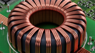
A common mode choke uses two insulated windings on one magnetic core, often with a 1:1 turns ratio. In a typical mains design, one winding carries line current and the other carries neutral current. Their directions are arranged so normal, equal-and-opposite currents create opposing magnetic flux. The flux largely cancels, allowing the intended power current to pass. When common-mode noise travels in the same direction on both conductors, the flux adds instead. The core then presents greater impedance to that unwanted noise.
The 1:1 ratio does not mean the choke blocks every unwanted signal equally. Core material, winding layout, and parasitic capacitance shape its performance across frequency. CISPR 32:2015+A1:2019 specifies Class B AC-mains conducted-disturbance limits of 66 to 56 dBµV from 150 to 500 kHz, illustrating why filtering must be checked across a defined band. A schematic makes the magnetic action look tidy; real layouts can behave less neatly.
Tips: Check the datasheet’s impedance-versus-frequency curve, then verify the assembled device with conducted-emissions testing. Keep both conductors close through the choke, and avoid routing noisy traces around it. The core is not magic.
How Common-Mode Flux Adds While Differential-Mode Flux Cancels
A common-mode choke uses two windings on one magnetic core. Their polarity makes the magnetic result depend on current direction. When equal differential currents flow out and return, their magnetomotive forces oppose each other. The core flux largely cancels, so the wanted signal sees relatively little impedance. Common-mode currents travel in the same direction on both conductors. Their magnetic forces reinforce each other, creating greater core flux and impedance that resists noise. The effect is simple, but winding balance and core properties matter.
That distinction matters in real equipment. A motor cable may carry switching noise along both wires, while the motor’s useful current forms an outgoing-and-returning pair. IEC 61000-4-6:2023 specifies conducted RF immunity testing from 150 kHz to 80 MHz, with test levels including 1, 3, and 10 V RMS, selected for the applicable environment and test plan. These figures do not prescribe a choke; they show why engineers check performance across frequency rather than relying on one inductance value.
Tips: Check the choke’s impedance curve at the noise frequency, then verify it in the assembled circuit. Keep paired conductors close together through the core. A small layout change can alter parasitic capacitance, so a bench measurement is still worth doing. I would not treat ideal flux cancellation as perfect: winding mismatch and leakage flux leave some differential impedance.
What Is a Common Mode Choke and How Does It Work?
How common-mode flux adds while differential-mode flux cancels
Illustrative normalized flux values: common-mode currents produce fluxes in the same direction, so they add in the core. Differential-mode currents produce opposing fluxes, so their net core flux is approximately zero.
How to Read Ratings: Impedance at 100 MHz, Rated Current, and DCR
A common mode choke is often described by its impedance at 100 MHz, but that number is only one point on a frequency curve. It indicates how strongly the part opposes common-mode noise near that frequency, not how much noise it will remove in every circuit. A choke rated 1,000 ohms at 100 MHz may behave quite differently at 5 MHz or above its self-resonant frequency. Check the impedance curve, if available. That detail matters.
Rated current tells you how much current the choke can carry under specified conditions, often tied to a permitted temperature rise. It is not a universal safe-current guarantee. A warm enclosure, limited airflow, or nearby heat sources can push winding temperature higher. In a real board, leave margin and check the manufacturer’s test conditions. A quick bench test can reveal surprises, but it cannot replace thermal testing in the final assembly.
DCR, or direct current resistance, is the winding’s resistance to steady current. Higher DCR creates voltage drop and heat, calculated as current squared times resistance. For example, 0.1 ohm at 1 amp produces 0.1 volt of drop and 0.1 watt of heat per winding. Compare DCR with your allowable loss, and confirm whether the listed value applies to each winding. Small differences can also matter when the two windings need balanced behavior. Ratings help narrow the choice; actual performance still depends on layout and noise frequency.
Application Context: CISPR 32 Conducted-Emission Testing from 150 kHz to 30 MHz
CISPR 32 conducted-emission testing checks disturbance voltage at relevant ports, including AC mains connections, from 150 kHz to 30 MHz. A line impedance stabilization network (LISN) provides a defined measurement setup. For Class B AC mains, CISPR 32:2015+A1:2019 lists quasi-peak limits that decline from 66 to 56 dBµV between 150 and 500 kHz; average limits decline from 56 to 46 dBµV. From 500 kHz to 5 MHz, the limits are 56 dBµV quasi-peak and 46 dBµV average (Table A.9). Limits depend on equipment class and port.
A common mode choke places two windings on a shared magnetic core. Common-mode noise currents create reinforcing magnetic flux, so the choke presents impedance to that noise. Normal differential currents create opposing flux, ideally allowing useful power to pass with little added impedance. On a test bench, a choke may reduce a noisy peak, but its performance depends on frequency, wiring, and nearby components. It is not a cure-all.
Tips: Compare measurements with the same LISN, cable position, load, and detector settings. Check the choke’s impedance across the problem frequencies, not just at one headline value. Small layout changes matter. If the result worsens, revisit parasitic paths and filter placement.