What Are the Top Current Transformer Core Types in 2026?
Choosing a Current Transformer Core in 2026 is not about finding one universal winner. The right choice depends on accuracy, current range, frequency, burden, and installation conditions. These details affect whether a core measures steadily or approaches saturation during faults. Small differences matter. An instrument transformer used for revenue metering may need different performance from one supporting protection or monitoring.
Common options include wound, toroidal, split-core, laminated-steel, amorphous, and nanocrystalline designs. Each offers trade-offs in accuracy, size, cost, losses, and ease of installation. Toroidal cores can provide compact magnetic paths, while split-core versions can simplify retrofit work when conductor access is limited. High-permeability alloys may reduce excitation current, but cost and handling requirements can affect project decisions. Silicon steel remains a familiar choice, though performance depends on grade, geometry, and operating frequency. Labels alone cannot settle the choice. Not every catalog claim translates into a better field result.
The complete transformer, its rating, and verified test data matter as much as the core material. Installation conditions, temperature, and nearby magnetic fields can also affect readings. A neat ranking can still mislead. This overview compares leading core types, explains their practical strengths and limitations, and identifies the details worth checking against the intended application. Manufacturer specifications and application-specific testing should guide the final selection.
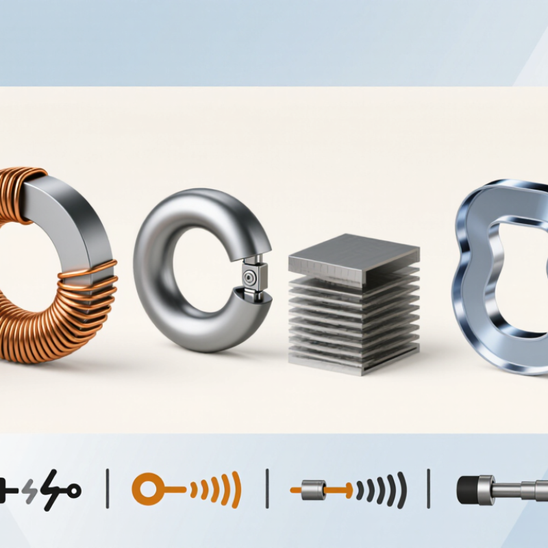
How Current Transformer Cores Support Measurement and Protection
Current transformer cores guide magnetic flux from a primary conductor into a secondary winding, producing a current signal for meters or protective relays. Their design affects accuracy, usable range, and response during faults. Laminated silicon steel is common in many conventional applications. Amorphous or nanocrystalline materials can offer lower core losses, especially at smaller currents, but suitability depends on the operating conditions.
There is no universally best core. Selection should consider rated current, frequency, accuracy class, and the connected burden, including leads and instruments. Small details matter.
Measurement cores are designed to reproduce normal load current accurately. Protection cores must also handle high fault currents without saturating too early. Their performance is often assessed using excitation characteristics and knee-point voltage, alongside the relay’s requirements. Some transformers use separate cores for measurement and protection, helping each circuit meet its own needs.
During installation, correct polarity and secure secondary connections are essential. A neat calculation can still miss a loose terminal or a longer-than-expected cable run. Check the completed circuit.
Never leave an energized current transformer’s secondary open; dangerous voltage may develop.
Which Materials Are Used in Current Transformer Cores?
Current transformer core material affects accuracy, saturation behavior, losses, and size. Electrical-grade silicon steel remains common in power-frequency applications. Its laminated sheets guide magnetic flux while limiting eddy-current losses. Grain-oriented grades can perform well when flux follows the rolling direction, though joint design and assembly also matter.
Nickel-iron alloys suit some sensitive measuring cores because they offer high permeability and low magnetizing current. Amorphous and nanocrystalline alloys can provide low core losses, especially where compact size or precise measurement is important. Their thin ribbons require careful handling and manufacturing. Small details matter. Core shape, annealing, air gaps, and operating flux density can change results as much as the alloy itself.
Material choice should match the transformer’s frequency, current range, accuracy target, and fault conditions. A core that performs well at low current may approach saturation during a heavy fault. That trade-off is easy to overlook. Published material figures help, but they do not fully predict a finished transformer’s behavior. Testing the assembled unit under realistic conditions is more dependable than choosing by material name alone. There is no universally best core; even familiar design rules deserve a second look when requirements change.
What Are the Main Core Designs: Wound, Toroidal, and Split-Core?
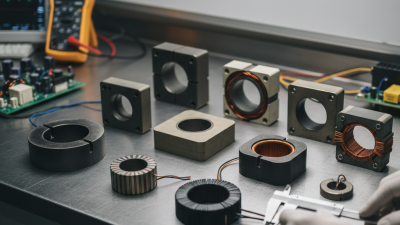
Wound, toroidal, and split-core designs solve different installation problems. A wound-core current transformer has primary and secondary windings arranged around a magnetic core. Its defined turns ratio can suit lower-current circuits or applications requiring a compact, purpose-built assembly. Winding layout and core material affect performance, but the design name alone does not guarantee accuracy. Check the rated burden and frequency range against the connected instruments.
Toroidal CTs use a ring-shaped core. The primary conductor usually passes through the center, acting as a single turn. This makes the design compact and common in panels where the conductor can be routed through the opening. Keep the conductor centered when practical, and follow the specified polarity. Small installation details matter.
A split-core CT opens around an existing conductor, so the circuit usually need not be disconnected for fitting. That convenience helps with retrofits, especially where cables are already crowded. Yet the mating faces must close fully; a visible gap can affect measurement. Not every retrofit is simple. Check conductor size, insulation clearance, and the CT’s accuracy class before installation. For dependable readings, compare measurements with expected load conditions and review any unusual deviations rather than assuming the core type explains them.
How Do Core Materials and Designs Affect CT Performance?
A current transformer’s core determines how faithfully primary current becomes a measurable secondary signal. Laminated silicon steel remains a practical choice for many metering and protection duties. It offers solid performance at a manageable cost, though its magnetic properties can limit accuracy when currents vary widely. Nanocrystalline alloys provide high permeability and low excitation current, which can support compact designs and precise measurement. Amorphous alloys can reduce core losses, but their behavior depends on construction and operating conditions. No material wins everywhere.
Geometry matters as much as the alloy. A closed toroidal core gives magnetic flux a continuous path, while a wound core can be tailored for particular accuracy or current requirements. Split-core designs are easier to install around existing conductors, but the mating surfaces create joints. Tiny gaps or uneven closure can increase magnetizing current and affect measurement. That can be frustrating. Core area, winding turns, and secondary burden also shape performance; too much burden can push the core toward saturation.
For protection CTs, saturation during a fault can distort the secondary waveform just when relays need dependable information. Metering CTs instead prioritize accuracy across their specified operating range. Engineers should compare excitation curves, accuracy class, burden, and short-time ratings against the actual installation. Catalog values help, but they cannot capture every cable layout or temperature. A careful review of the complete operating conditions is still needed. There is no perfect core.
What Are the Top Current Transformer Core Types in 2026?
Core material and construction affect a current transformer’s magnetic capacity, accuracy, and response to fault currents. The chart compares representative saturation flux density values for commonly used core materials.
Values are indicative typical ranges represented by approximate midpoints; actual properties vary by grade, processing, and operating temperature. Toroidal cores generally provide a continuous magnetic path, while split-core joints and air gaps can reduce effective permeability. Laminated electrical steel helps limit eddy-current losses.
How to Choose a Current Transformer Core for an Application
What Are the Top Current Transformer Core Types in 2026?
How to Choose a Current Transformer Core for an Application
Choosing a current transformer core starts with the job it must do. Metering cores need dependable accuracy across the expected operating range. Protection cores must respond predictably during fault conditions without saturating too early. Solid-core designs suit new installations, while split-core designs can simplify retrofits around an existing conductor. Construction matters, but the full transformer design matters more.
Match the core to the system’s primary current, frequency, required accuracy, and connected burden. Check the equipment specifications, including the accuracy class and rated burden in volt-amperes. A long cable run or several connected devices can increase burden and affect performance. Core materials such as silicon steel, amorphous metal, or nanocrystalline alloys each have different magnetic properties. The material alone does not guarantee accuracy. A detail easy to miss: fault current and remanent magnetism can affect whether a protection core meets its intended performance.
Tips: Confirm conductor size and available mounting space before selecting a core. Compare the specified burden with the actual connected load, including wiring. Ask for test data when accuracy is critical. Then review the choice against real operating conditions; paper calculations can miss awkward installation details. When requirements are uncertain, consult a qualified electrical engineer and verify the complete CT specification.