inquiry
Leave Your Message

What Are the Best Instrument Transformers in 2026?

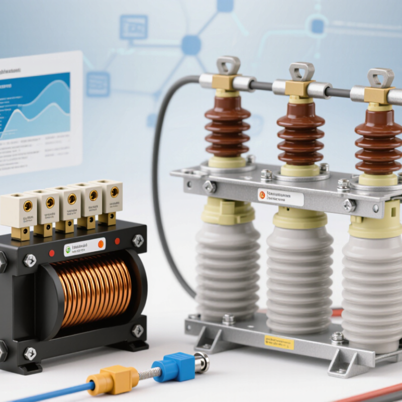
Choosing the best Instrument Transformers in 2026 is not simply a matter of comparing brands. The right unit must match its electrical duty, installation environment, and measurement requirements. A current transformer serving a protection relay has different priorities from a voltage transformer used for revenue metering. Small details matter.

This guide examines practical selection points, including ratio accuracy, insulation level, rated burden, thermal performance, and indoor or outdoor construction. For example, a metering circuit may require a specific accuracy class, while a protection application may depend on the transformer’s ability to reproduce fault current without unacceptable saturation. A datasheet deserves careful reading. A low purchase price can look attractive, yet create problems if the selected burden or terminal arrangement does not fit the system.

The comparison also considers maintenance, documentation, and manufacturer support. These factors are easy to overlook when specifications appear similar. Check test reports, nameplate ratings, connection diagrams, and applicable project requirements before making a purchase. Where the installation is unusual, confirm critical values with a qualified engineer or the manufacturer. No single model is best for every network. Even a well-researched shortlist has limits, because regional availability and project conditions change. The aim here is a useful, evidence-led starting point—not a substitute for site-specific engineering review.
What Are the Best Instrument Transformers in 2026?

Instrument Transformers: Purpose, Design, and Operating Principles

Instrument transformers make high-voltage systems measurable. Current transformers reduce large line currents to manageable secondary values; voltage transformers step down system voltage. This lets meters, relays, and control equipment monitor circuits without direct connection to primary conductors. Small devices. Serious responsibility.

A typical current transformer uses a magnetic core around a conductor. Its secondary winding supplies a current proportional to primary current, while a voltage transformer produces a reduced, proportional voltage. Core material, winding geometry, insulation, and burden ratings affect accuracy and performance. IEC 61869 sets requirements for instrument transformers, including accuracy classes and testing. In field work, engineers also check polarity, grounding, and the connected burden. An energized current transformer’s secondary must not be left open; dangerous voltage can develop.

Grid expansion makes dependable measurement increasingly important. The International Energy Agency’s 2023 report, Electricity Grids and Secure Energy Transitions, says annual grid investment needs to rise from about USD 300 billion to more than USD 600 billion by 2030. That figure covers grids broadly, not instrument transformers alone. Still, it highlights the scale of infrastructure requiring reliable monitoring. Selection is not just a ratio exercise: transient performance, environment, and protection needs matter. One uncomfortable detail is that a correctly specified unit can still mislead when installation or wiring is wrong.

Current and Voltage Transformers: Types and Key Differences

Current and voltage transformers both scale electrical values for meters and protective relays, but they work in different parts of a circuit. A current transformer (CT) is connected in series and produces a smaller current that follows the primary current. Common designs include wound, bar, and window types. A voltage transformer (VT) is connected in parallel and steps high voltage down to a measurable level. Electromagnetic and capacitive designs suit different voltage ranges and installation needs.

That distinction matters. A CT’s secondary must not be left open while its primary is energized, because dangerous voltage can develop. A VT secondary, by contrast, must not be short-circuited. In a substation, the CT may sit around a busbar, while a VT connects across conductors. Their jobs differ, even when both feed the same protection panel.

Choosing well means checking the transformation ratio, accuracy class, burden, insulation level, and operating environment. Metering may require close accuracy at ordinary load, while protection transformers must respond reliably during faults. Small details count. Cable length and connected devices affect burden, and a good paper specification cannot replace careful installation checks. The “best” type depends on the circuit, measurement purpose, and site conditions—not a single universal ranking.

Criteria for Evaluating Instrument Transformers in 2026

The best instrument transformer in 2026 is the one that matches the measurement task, not simply the highest accuracy class. Start with system voltage, primary current, frequency, and the meter or relay’s required input. Then check ratio accuracy and phase displacement across the expected operating range. A transformer may perform well near its rated load but less well when actual burden is low or wiring runs are long.

Fit matters. For current transformers, compare rated burden and short-time thermal and dynamic withstand against the installation’s conditions. For voltage transformers, review insulation level, accuracy, and suitability for the connected protection or metering circuit. Check ambient temperature, humidity, mounting space, and cable routing too. A cramped panel can make a technically sound choice awkward to install. Small details count.

Ask for test records and confirm that ratings align with applicable standards and project specifications. Look for clear data on accuracy, insulation, temperature rise, and, where relevant, partial-discharge performance. Verify that the complete secondary circuit—including leads and connected devices—stays within the specified burden. Field measurements can reveal surprises. They do not replace design checks, though. Even careful selection has limits; operating conditions and installation workmanship can shift performance, so leave room to question assumptions.

Leading Instrument Transformer Options by Application

What Are the Best Instrument Transformers in 2026?
Leading Instrument Transformer Options by Application

The best instrument transformer depends on the job, not a single ranking. Current transformers suit feeder protection and metering, where they reduce high line current to a measurable signal. For a switchgear panel, engineers should check the required accuracy class, rated burden, short-circuit withstand, and available mounting space. A compact unit may fit neatly but leave little room for wiring or future inspection.

Voltage transformers are common in substations and distribution systems, providing scaled voltage for meters, relays, and control equipment. Indoor installations may prioritize insulation and clearances, while outdoor units must handle moisture, temperature swings, and contamination. Combined current-and-voltage transformers can save space at a constrained site, though maintenance access deserves a close look. Space savings are not everything.

For digital protection and monitoring, low-power electronic instrument transformers can provide signals suited to modern measurement systems. Compatibility matters: confirm the connected relay or meter accepts the output type and operating range. In any application, compare accuracy across the actual load range, not just at one convenient test point. Specifications can look reassuring on paper. They still need checking against site conditions, protection settings, and the utility’s requirements. When those details are uncertain, a qualified engineer should review the selection before installation.

What Are the Best Instrument Transformers in 2026? - Leading Instrument Transformer Options by Application

Application Suitable Instrument Transformer Why It Fits Key Selection Criteria Typical Accuracy Considerations
Revenue and energy metering Metering current transformer (CT) and voltage transformer (VT) Provides scaled current and voltage inputs for meters while electrically isolating measuring equipment from the primary circuit. Required current and voltage ratios; meter burden; system voltage; installation environment; calibration and applicable utility requirements. Choose a metering accuracy class specified by the applicable standard and project requirements. CT classes such as 0.2S or 0.5S are used in some IEC applications; confirm performance at the actual burden and operating range.
Overcurrent and earth-fault protection Protection CT Designed to provide relay inputs during fault conditions, with performance selected to limit unacceptable saturation for the protection scheme. Maximum prospective fault current; relay input and burden; CT ratio; protection function; transient performance; knee-point or accuracy-limit requirements where applicable. IEC protection classes include 5P and 10P for specified composite-error limits at the accuracy-limit current. The required class and limit factor depend on the relay and system study.
High-voltage transmission voltage measurement Capacitor voltage transformer (CVT/CCVT) Uses a capacitive divider with an electromagnetic unit to provide a reduced voltage signal; commonly used on high-voltage transmission systems and may also support carrier-frequency coupling designs. System voltage and insulation level; measurement and protection needs; transient response; ferroresonance mitigation; frequency response; applicable coupling requirements. Verify the specified voltage-transformer accuracy class, rated burden, and frequency range. Measurement and protection winding requirements may differ.
Substation voltage measurement and protection Inductive voltage transformer (VT/IVT) Provides an isolated, reduced voltage signal for meters, relays, and control equipment; commonly selected where an inductive design suits the voltage level and installation. System voltage; insulation and grounding arrangement; primary connection; secondary winding count; burden; indoor or outdoor service conditions. Specify the required metering or protection class for each secondary winding. IEC examples include 0.2 or 0.5 for measurement and 3P or 6P for protection, subject to rated conditions.
Digital substation and process-bus systems Low-power instrument transformer (LPIT) or electronic instrument transformer Can provide low-level analogue or digital measurement signals for compatible merging units and protection or measurement systems. Signal interface; interoperability with the substation architecture; power supply; electromagnetic compatibility; environmental ratings; lifecycle support and relevant IEC 61869 requirements. Check the specified performance class and system accuracy for the complete measurement chain, including sensor, interface, merging unit, and connected IED.
Generator differential and busbar protection Matched protection CT set Consistent CT characteristics across protection zones help the differential scheme distinguish internal faults from normal load and external faults. CT ratios and polarity; winding arrangement; burden; transient response; saturation behavior; relay settings; layout and wiring consistency. Use the protection scheme designer’s specified class or special CT requirements. For schemes requiring defined excitation characteristics, confirm the required knee-point voltage and secondary resistance.

Selection note: There is no single best instrument transformer for every installation. Confirm ratings, accuracy, insulation coordination, burden, environmental conditions, and applicable IEC 61869 or IEEE C57.13 requirements with the project specification and protection or metering study.

How to Select an Instrument Transformer for a Power System

What Are the Best Instrument Transformers in 2026?

How to Select an Instrument Transformer for a Power System

Choosing an instrument transformer starts with its job: measurement, protection, or both. A current transformer must match expected load current and withstand the maximum fault current without unacceptable saturation. A voltage transformer must suit system voltage, grounding, insulation level, and transient conditions. Check accuracy class and secondary burden against the connected meters and relays, not just catalogue values. Small details matter.

System growth also affects selection. The U.S. Department of Energy’s 2023 National Transmission Needs Study says transmission capacity could need to grow about 57% by 2035 under a high-clean-energy scenario. NERC’s 2024 Long-Term Reliability Assessment projects North American summer peak demand will rise by roughly 132 GW over ten years. These projections make future load, fault levels, and expansion plans relevant to today’s rating choices.

Compare designs against IEC 61869 requirements, then verify performance for the actual installation. Check temperature, altitude, pollution, moisture, and available space; a unit that fits electrically may still fail the site conditions. For example, confirm that secondary wiring length keeps burden within limits, and test polarity and ratio during commissioning. Calculations can look clean on paper. Field conditions are less tidy, so document assumptions and review them when the network changes.