How to Choose the Right Transformer Core for Your Needs?
Choosing a Transformer Core is not a materials decision alone. It shapes energy losses, temperature rise, sound, size, and lifetime cost. The U.S. Department of Energy’s 2016 distribution-transformer analysis reports that amorphous-metal cores can reduce no-load losses by roughly 60–70% compared with conventional designs. That figure is useful, but it is not a promise for every unit. Core geometry, steel grade, manufacturing quality, and operating conditions all matter.
A practical paraphrase of transformer-design expert George G. Karady’s published work is: “Match the core design to the actual load and operating conditions.” Treat that as a guiding principle, not a verbatim quotation. A lightly loaded transformer may spend long hours paying for core losses, while a heavily loaded unit also needs careful attention to winding losses and heat. The right choice depends on the duty cycle, required efficiency, available space, noise limits, and budget.
Start with the real operating profile. Check average and peak load, expected annual hours, and the cost of energy losses. Then compare silicon-steel and amorphous-metal options using the same rating and test conditions. Ask suppliers for documented loss figures, tolerances, and supporting test reports. Small differences matter over years. Yet specifications can look cleaner than factory reality; independent verification is worth considering. A core should fit the application, not just the spreadsheet.
Understanding the Role of a Transformer Core
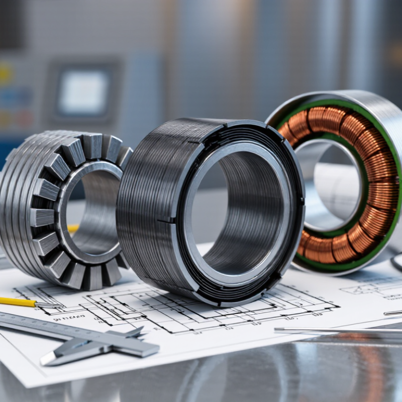
A transformer core provides a controlled path for magnetic flux between the primary and secondary windings. Without it, much of the magnetic field would spread into the surrounding air, reducing efficiency and increasing the energy needed to transfer power. The core does not create electricity; it helps couple the windings so changing current in one can induce voltage in the other. This is its central job.
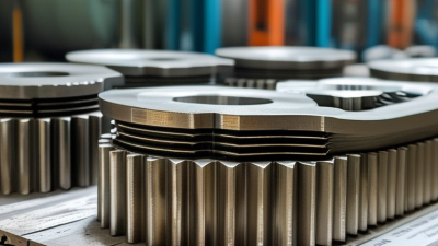
Core material and shape affect performance. Laminated silicon steel is common in power-frequency transformers because thin, insulated layers help limit eddy currents and heat. Ferrite is often used at higher frequencies, where its magnetic properties can suit compact designs. The core’s cross-sectional area also matters: too little area can push the material toward saturation, causing higher magnetizing current, extra noise, and heat. A hum is a clue, not a complete diagnosis.
Choosing a core means matching material, size, frequency, and expected load to the application. For example, a small control transformer in a warm cabinet faces different demands from a continuously loaded unit in a ventilated room. Check operating temperature, duty cycle, and allowable losses against the design data. In practice, the neat calculation may not capture every installation condition; enclosure airflow and real load variation can change results. That uncertainty deserves a margin, not a guess.
Matching Core Properties to Electrical Requirements
Choosing a transformer core starts with the electrical job, not the material name. Match it to the operating frequency, voltage, waveform, and expected load. A 50/60 Hz power transformer often uses laminated electrical steel to limit eddy-current heating. A high-frequency converter may use ferrite, whose high resistivity helps reduce those currents. Small details matter.
Check the expected flux density against the core’s saturation limit. The design must tolerate peak voltage and current, including startup or distorted waveforms. If flux runs too high, magnetizing current can rise sharply, creating noise and heat. Lowering flux may require a larger core or more turns, affecting size, copper loss, and cost. There is no free gain.
Compare core loss at the actual frequency and flux density, rather than relying on one catalog figure. Consider temperature rise, cooling, duty cycle, and insulation requirements as well. Amorphous alloys can reduce core loss in some mains-frequency designs, but handling and availability may complicate the choice. It still depends. Check manufacturer data curves, then test a prototype under realistic load; calculations may miss variations in winding or assembly.
Evaluating Size, Efficiency, Cost, and Operating Conditions
Choosing a transformer core starts with the required voltage, power rating, and available space. Core cross-section affects flux density, while the window must accommodate windings and insulation. A compact design may reduce material use, but it can leave less room for cooling. Small margins matter.
Efficiency depends on both core and winding losses. Silicon steel is common in many power-frequency designs; amorphous materials can reduce no-load losses but may cost more and require different handling. Compare losses at expected loads, not just at rated output. A low purchase price can become expensive when a unit runs continuously. Actual savings depend on its duty cycle and electricity costs.
Operating conditions can change the best choice. High ambient temperatures, limited airflow, vibration, and frequent load changes all affect performance. Harmonics can increase heating, so a core selected for a clean sinusoidal supply may not suit every installation. Heat matters. Check the operating frequency and the manufacturer’s loss data, and have a qualified electrical engineer verify the design against the real load profile. In practice, measurements from an existing installation can reveal problems that a tidy spreadsheet misses.
Checking Compatibility with the Transformer’s Intended Use
A transformer core should match the job it will perform, not just its rated power. Start with the intended voltage, frequency, load range, and operating schedule. A unit running continuously in a warm control cabinet faces different demands from one used intermittently in a cool workshop. Core material and geometry affect magnetizing current, losses, and heat, so compare manufacturer data at the actual operating frequency and flux density.
Check the full electrical conditions. A core designed for one frequency may overheat if driven at a lower frequency with the same voltage. That detail is easy to miss. Also consider waveform shape, since distorted input voltage can increase heating. For a compact supply, size and weight may matter; for a quiet indoor installation, audible hum may deserve more attention. Allow room for insulation, windings, and cooling rather than choosing by core dimensions alone. Measure the enclosure and check clearances. Real installations are rarely perfect. If the load changes, or the transformer must tolerate frequent starts, ask a qualified designer to verify temperature rise and saturation margins. A small mismatch can become a persistent heat problem.