How to Choose the Right Current Transformer Core in 2026?
In 2026, choosing a Current Transformer Core means matching electrical performance to the real operating conditions of the installation. A core that looks suitable on a datasheet may behave differently under high fault current, continuous load, or a wide range of primary currents. Small details matter. Core material, magnetic path area, accuracy class, burden, and saturation limits all affect measurement quality and protection response.
Start with the intended use: metering, monitoring, or protective relaying. Then compare rated current, secondary output, frequency, insulation requirements, and connected burden. For protection, review the required accuracy and saturation behavior during fault events. For metering, check performance near normal operating load, not only at rated current. Ask suppliers for test data and clear definitions of their ratings. This helps distinguish verified performance from marketing language. Consider installation space, temperature, vibration, and nearby conductors, too. These details can influence fit and operation. Check carefully.
There is no universal best core. A compact design may save panel space, yet leave less margin for demanding conditions. A high-accuracy option may add cost without improving the system if surrounding equipment is not equally capable. That trade-off deserves a second look. This guide explains key specifications, common selection errors, and practical questions to ask before ordering. Check recommendations against the project design and manufacturer documentation, because application details can change the right choice.
Define the Measurement and Protection Requirements
Before selecting a current transformer core, define what the circuit must measure and what it must protect. Metering cores prioritize accuracy near normal operating current. Protection cores must reproduce fault current long enough for relays to respond. One core may not serve both jobs well. Specify the primary and secondary current ratings, frequency, accuracy class, and connected burden. Include lead length and relay or meter input, since their combined burden affects performance. For protection, check the expected fault current and the core’s saturation characteristics. A core that saturates too early can distort the signal when protection is needed most. That is not enough.
Tips: Start with the actual system data, not a generic core size. Confirm the maximum continuous current, fault level, and required relay response with the electrical design team. If readings seem inconsistent, revisit the assumed burden and wiring length before changing the core.
Also check the physical installation. Measure the conductor or busbar, available mounting space, and insulation clearances. A technically suitable core can still be difficult to install or maintain. This detail is easy to miss when selection happens from a datasheet alone. Record assumptions, especially where fault data or future load growth is uncertain. A careful review with the equipment supplier or a qualified electrical engineer can resolve gaps before procurement. Avoid treating “higher accuracy” as automatically better; the required class depends on the application and operating range. Small details matter.
Compare Current Transformer Core Materials and Designs
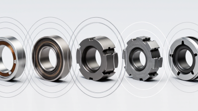
Choosing a current transformer core means balancing accuracy, size, cost, and installation needs. Silicon steel is a practical choice for many 50 or 60 Hz applications. It is widely available and handles higher magnetic flux than many high-permeability alloys, but may need more core area or winding turns to meet tight low-current accuracy targets. Details matter.
Nanocrystalline cores offer high permeability and low magnetizing current, which can help compact designs measure small currents accurately. Amorphous alloys can also reduce core losses, though handling and manufacturing requirements may affect cost. These materials are not automatically better: saturation limits, operating temperature, waveform distortion, and the specified accuracy class all deserve review. A datasheet alone can mislead.
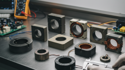
Core shape changes the installation trade-off. A closed toroidal core provides a continuous magnetic path and is often suited to precision measurement, but fitting it may require disconnecting the conductor. A split-core design opens around an existing cable, making retrofit work easier. The joint is a weak spot; dust, uneven closure, or a small gap can affect readings. Check the assembled unit, not just the material. In practice, a few millimetres of clearance can decide whether a core fits inside a crowded panel. I would still verify performance at the actual load range, because laboratory conditions rarely match every installation.
How to Choose the Right Current Transformer Core in 2026? - Compare Current Transformer Core Materials and Designs
Compare core materials and construction styles against the required frequency, accuracy, installation method, and operating conditions. Material properties and performance are indicative; actual results depend on core geometry, heat treatment, winding, burden, and manufacturer specifications.
Comparison of Current Transformer Core Materials
| Core material |
Typical characteristics |
50/60 Hz suitability |
Accuracy and excitation behavior |
Relative cost |
Common applications and trade-offs |
| Grain-oriented silicon steel (CRGO) |
Laminated electrical steel; high flux capability and mature manufacturing process. |
Excellent; widely used at power frequency. |
Can provide dependable metering or protection performance when correctly designed; performance is sensitive to joints, stress, and assembly. |
Low to medium |
A practical choice for many conventional CTs. Laminations and joints can increase size and affect magnetizing current. |
| Amorphous metal |
Very thin, non-crystalline ribbon with low core loss under suitable operating conditions. |
Good; available in power-frequency CT designs. |
Low loss can support low excitation requirements, but achievable accuracy depends on processing, winding, and the finished core. |
Medium to high |
Useful where low losses are valued. Ribbon is relatively brittle and can be more difficult to cut or handle than conventional laminations. |
| Nanocrystalline alloy |
High permeability and low coercivity can be achieved in a compact wound core; properties depend on alloy and annealing. |
Excellent in purpose-designed power-frequency CTs. |
Often suitable for sensitive measurement designs with low excitation current; verify accuracy over the specified current and burden range. |
Medium to high |
Good option for compact, high-performance measurement CTs. Thin ribbon and heat treatment require controlled manufacturing. |
| Nickel-iron alloy (permalloy family) |
Very high permeability is possible after suitable processing; saturation flux density is generally lower than that of silicon steel. |
Good for specialized power-frequency designs. |
Can deliver low excitation current and high sensitivity, but may need careful sizing to avoid saturation at high current or DC offset. |
High |
Used in specialized low-level or high-accuracy measurement applications. Usually not the default choice for cost-sensitive general-purpose CTs. |
Comparison of Core Designs
| Core design |
Construction |
Main advantages |
Main limitations |
Best suited to |
| Continuous toroidal (wound) core |
Magnetic strip or ribbon wound into a closed ring, usually with a continuous magnetic path. |
No intentional air gap; compact construction and potentially low excitation current. |
Conductor installation generally requires access to an end of the conductor before connection. |
New equipment, compact metering CTs, and applications prioritizing a closed magnetic path. |
| Split-core |
Core separates into sections so it can be fitted around an existing conductor. |
Can be installed without disconnecting the conductor; convenient for retrofit work. |
Mating surfaces and closure pressure affect the magnetic path; alignment and cleanliness matter for repeatable performance. |
Retrofits, temporary monitoring, and installations where conductor disconnection is impractical. |
| Cut-core |
A previously formed core is cut and reassembled around the conductor; cut faces form a joint. |
Combines retrofit access with a core that can be manufactured and wound before installation. |
Joint quality and closure consistency can influence excitation current, ratio error, and phase displacement. |
Retrofit measurement where a compact, pre-wound CT is preferred. |
| Laminated stacked core |
Stamped or cut electrical-steel laminations assembled into a closed or jointed magnetic path. |
Robust, scalable construction with established manufacturing methods and a range of shapes. |
Joints, stacking factor, burrs, and mechanical stress can affect magnetic performance; often larger than a wound core for a comparable design. |
General-purpose CTs, larger assemblies, and designs requiring robust, repeatable construction. |
Selection check: Confirm the CT’s rated primary and secondary currents, accuracy class, burden, frequency, insulation level, short-time thermal and dynamic ratings, and required installation method. For protection duties, also verify the specified accuracy-limit or knee-point performance and the effects of remanence and fault-current offset.
Match Core Ratings to Current, Frequency, and Burden
How to Choose the Right Current Transformer Core in 2026?
Match the core’s current rating to the real operating range, not only the nominal load. A core that is too small may saturate during current peaks and distort the secondary waveform. An oversized core can compromise accuracy at low currents in some designs. Check the ratio, accuracy class, and expected overload conditions together.
For example, a 100:5 CT ideally delivers about 2 amps at its secondary when the primary carries 40 amps. That relationship holds only within the CT’s specified limits.
Frequency and burden matter just as much. A core designed for one frequency may show different errors at another, so verify its rating against the system frequency and waveform. Burden is the total load connected to the secondary, including meters, relays, and lead resistance. Long, thin wires can add noticeable burden. If the connected load exceeds the CT’s rated VA, measurement accuracy may suffer. Small details can change the result.
Tips: Add up instrument and cable burdens before choosing a core. Compare that total with the CT’s rated burden, and leave some margin where practical. Check manufacturer test data for the intended current and frequency; a single headline accuracy figure may not describe every operating point. I would still review the actual installation conditions, because calculations rarely capture every cable run or load change.
Verify Installation Conditions and Applicable Standards
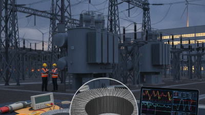
A current transformer core should match the conditions where it will operate, not just the nominal current on a drawing. Inspect the panel or switchgear: note conductor size, available clearance, ambient temperature, vibration, and whether the core fits around an insulated or busbar conductor. Small details matter. Measure the full secondary burden, including meter inputs and lead length, then check the required accuracy class and fault-current performance. A cramped enclosure can also affect access and heat dissipation. Do not assume a catalog rating covers every installation.
Verify the applicable standard and its current edition against the project specification and local requirements. IEC 61869-2 and IEEE C57.13 are common references for instrument transformers, but acceptance criteria may differ by application. Match the core’s ratio, insulation level, frequency, and accuracy requirements to the selected standard. During commissioning, confirm polarity, grounding, terminal identification, and actual wiring. Never leave an energized CT secondary open. One practical limitation: field conditions are sometimes recorded poorly. Photographing the conductor layout and documenting measured lead lengths can prevent avoidable selection errors, though it cannot replace a qualified engineering review.
How to Choose the Right Current Transformer Core in 2026? — Verify Installation Conditions and Applicable Standards
Check the CT’s rated secondary current, connected lead burden, and applicable project requirements before selecting a core.
Calculated cable-only burden for 2.5 mm² copper conductors at 20°C, using a round-trip circuit and copper resistivity of 0.0175 Ω·mm²/m. Burden is I²R: at the same cable length, a 5 A secondary produces 25 times the lead burden of a 1 A secondary. Actual total burden also includes connected instruments and terminals. IEC 61869-2 covers current-transformer requirements; confirm the applicable edition, rated secondary current, accuracy class, and burden against the project specification.