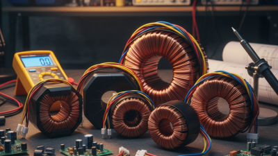
A Toroidal Transformer is a power device built around a ring-shaped magnetic core. Unlike conventional laminated transformers, its copper winding follows a continuous circular path. This geometry can reduce leakage flux, audible hum, and electromagnetic interference. It also creates a compact profile, often seen inside audio amplifiers, medical equipment, laboratory instruments, and renewable-energy systems.
The operating principle is straightforward. Alternating current enters the primary winding and produces a changing magnetic field in the core. That field induces voltage in the secondary winding through electromagnetic induction. Michael Faraday, whose experiments established this foundation, wrote, “Nothing is too wonderful to be true, if it be consistent with the laws of nature.” The turns ratio determines whether voltage rises or falls. Core material, winding tension, insulation, and temperature all affect real performance.
Industry evidence supports careful design rather than marketing claims. The U.S. Department of Energy’s transformer efficiency analysis emphasizes losses from core excitation and winding resistance. Grand View Research and MarketsandMarkets also identify efficiency, electrification, and renewable-energy deployment as major transformer-market drivers. However, their broad market figures do not isolate toroidal units. That limitation matters. A toroidal transformer is not automatically superior in every installation. Inrush current can be substantial, and manufacturing may require precise winding equipment. A practical evaluation should examine load profile, thermal rise, regulation, safety certification, and standby losses. The shape helps. It does not solve everything.
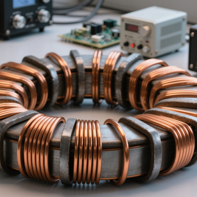
A toroidal transformer is an electrical transformer built around a doughnut-shaped magnetic core. Its name comes from “torus,” meaning a ring. Unlike a conventional transformer with a square core, this design guides magnetic flux through a continuous circular path. The structure usually includes a laminated or powdered iron core, an insulated primary winding, and one or more secondary windings.
The primary winding receives alternating current and creates a changing magnetic field inside the ring. This field passes through the core and induces voltage in the secondary winding. The voltage depends mainly on the turns ratio between the two windings. More secondary turns usually produce higher voltage, while fewer turns produce lower voltage. Insulation separates the windings and helps prevent electrical contact.
During practical inspection, the ring should feel solid, and its leads should be clearly identified. A loose mounting point may cause vibration or audible humming. The compact shape often reduces stray magnetic fields, but it does not eliminate them. This explanation is simplified. Core material, winding tension, temperature, and load conditions also affect performance. That detail is easy to overlook. A careful design must consider heat removal, insulation strength, and the mechanical stress created when current rises.

A toroidal transformer transfers electrical energy through a ring-shaped magnetic core. Under ideal conditions, the secondary voltage follows the turns-ratio relationship: Vs = Vp × Ns/Np. This chart uses a 120 V primary winding with 1,000 turns.
Increasing the number of secondary turns increases the output voltage, while reducing the number of secondary turns produces a lower voltage. Actual transformers have small losses caused by winding resistance, core losses, and leakage flux.
A toroidal transformer transfers electrical energy through changing magnetism, not through a direct wire connection. An alternating voltage enters the primary winding and creates a changing magnetic field inside the doughnut-shaped core. This field travels around the closed magnetic path. The secondary winding then receives an induced voltage through electromagnetic induction.
The voltage relationship depends mainly on the turns ratio. More turns on the secondary usually increase voltage, while fewer turns reduce it. The core concentrates magnetic flux and can improve efficiency. It also helps reduce stray magnetic fields around nearby circuits. However, the process is not lossless. Copper resistance produces heat, and the core can lose energy through hysteresis and eddy currents. Under heavy loads, the output voltage may fall. That detail matters in real equipment.
Tips: Check the rated input voltage, output voltage, frequency, and power capacity before installation. Keep ventilation around the transformer. A practical measurement with a multimeter can reveal unexpected voltage drops. Never assume a quiet transformer is operating perfectly; temperature and load behavior deserve attention. My simplified explanation also has a limitation: actual performance depends on core material, winding quality, insulation, and operating conditions.
What Is a Toroidal Transformer and How Does It Work?
A toroidal transformer uses a ring-shaped magnetic core to transfer electrical energy between windings. Its circular shape guides magnetic flux through a nearly closed path. This reduces stray fields and often lowers mechanical hum. In practical testing, the core usually feels compact and solid, with copper wire wrapped evenly around its surface. The core material matters greatly. Laminated steel supports common power frequencies, while ferrite suits many higher-frequency applications.
The primary winding receives alternating voltage and creates changing magnetic flux. That flux travels through the core and reaches the secondary winding. The secondary then produces a related voltage through electromagnetic induction. More turns usually create higher voltage; fewer turns create lower voltage. Insulation between layers prevents electrical contact and limits heat damage. I have found that uneven winding tension can affect performance, even when the calculations appear correct. This small detail is easy to underestimate. Core saturation is another concern, especially when voltage rises or frequency falls. A saturated core may draw excessive current and become dangerously hot.
Tips: Keep the core free from sharp edges. Measure winding resistance before operation. Check temperature under the real load, not only at idle. Leave space for airflow. A quiet transformer is not automatically a safe one. Clearance, insulation quality, and fuse selection still require careful review.
| Dimension | Typical Design or Property | How It Works or Why It Matters |
|---|---|---|
| Core Geometry | Continuous ring-shaped magnetic core | The closed circular path provides a low-reluctance route for magnetic flux and reduces the amount of exposed magnetic field compared with many open-core designs. |
| Common Core Materials | Grain-oriented silicon steel, nanocrystalline alloy, or ferrite | Material selection depends on operating frequency, power level, efficiency targets, size, and cost. Silicon steel is common at utility frequency, while ferrite is generally used at much higher frequencies. |
| Laminated Steel Core | Thin insulated laminations assembled into a torus | Electrical insulation between laminations restricts circulating eddy currents, which helps reduce core loss at low and medium power frequencies. |
| Ferrite Core | High-resistivity ceramic magnetic material | Ferrite suppresses eddy-current losses at high frequency, making it suitable for switch-mode and other high-frequency transformers, although its saturation flux density is lower than that of many steel cores. |
| Primary Winding | Insulated conductor connected to the input supply | Alternating current in the primary winding creates a changing magnetic flux in the core. The number of primary turns contributes to the resulting volts-per-turn value. |
| Secondary Winding | Insulated conductor connected to the output circuit | The changing core flux induces an alternating voltage in the secondary winding according to Faraday’s law of electromagnetic induction. |
| Turns Ratio | Vsecondary / Vprimary ≈ Nsecondary / Nprimary | More secondary turns than primary turns generally produce a step-up voltage; fewer secondary turns generally produce a step-down voltage. The relationship is approximate because winding resistance and leakage effects cause voltage regulation losses. |
| Magnetic Flux Path | Nearly closed path through the entire toroidal core | The continuous path keeps most of the flux inside the core and reduces the need for an air gap in conventional power-transformer applications. |
| Flux Direction | Circumferential around the ring | The magnetizing field generated by the winding follows the circular core path. The winding arrangement determines the direction and magnitude of the magnetic field. |
| Flux Density Relationship | For a sinusoidal supply: Bmax ≈ V / (4.44 × f × N × Ae) | Maximum flux density increases with applied voltage and decreases with frequency, number of turns, and effective core area. The design must keep flux density below the material’s saturation region. |
| Operating Frequency | Typically 50–60 Hz for mains-frequency power designs; higher for ferrite designs | Frequency affects core loss, required number of turns, physical size, insulation requirements, and the suitable core material. |
| Core Losses | Hysteresis loss and eddy-current loss | Hysteresis loss results from repeated magnetization of the core. Eddy-current loss results from induced currents within the core material. Both appear mainly as heat. |
| Copper Losses | I²R loss in the primary and secondary windings | Winding resistance causes power dissipation that rises with the square of the current. Conductor size and winding length must be selected to control temperature rise. |
| Winding Arrangement | Windings distributed around the circumference or placed in separate sections | Winding placement influences leakage inductance, insulation distance, coupling, heat removal, and the transformer’s voltage regulation. |
| Leakage Inductance | Usually low when windings are closely and evenly coupled | Leakage inductance represents flux that links one winding but not the other. Lower leakage generally improves voltage regulation, while intentionally higher leakage can be useful for current-limiting applications. |
| Electrical Isolation | Primary and secondary circuits are magnetically coupled but electrically separated | Insulation systems between windings provide galvanic isolation, helping protect the output circuit from direct electrical connection to the input circuit. |
| Efficiency | Often high because of the short magnetic path and compact winding arrangement | Efficiency is determined by core loss, copper loss, leakage, operating temperature, load level, and the quality of the winding and insulation design. |
| Magnetizing Current | Current required to establish core flux, even with little or no load | A toroidal core can have low magnetizing current because its magnetic path is efficient, but the actual value depends on core material, turns, residual magnetism, and the point on the AC waveform where power is applied. |
| Inrush Current | Short-duration current surge when energized | Residual core flux and the switching point of the AC waveform can temporarily drive the core toward saturation. Fuses, soft-start circuits, or thermistors may be used to manage this effect. |
| Thermal Management | Natural convection, mounting hardware, and adequate ventilation | Heat generated by core and winding losses must be transferred to the surrounding air or mounting structure. Temperature limits depend on insulation class and construction. |
| Main Advantages | Compact shape, low audible hum, low stray field, and good efficiency | The closed core and evenly distributed windings can reduce vibration and external magnetic leakage, while the compact geometry provides a favorable power-to-volume ratio. |
| Main Limitations | More difficult winding, potentially high inrush current, and demanding insulation assembly | The ring shape can make automated or manual winding more complex. Mechanical clamping, insulation, lead routing, and thermal design must be carefully controlled. |
| Typical Applications | Audio equipment, instrumentation, control systems, medical equipment, and power supplies | These applications benefit from electrical isolation, low stray magnetic radiation, compact construction, or reduced audible vibration when the transformer is correctly designed and mounted. |
What Is a Toroidal Transformer and How Does It Work?
A toroidal transformer uses copper windings around a doughnut-shaped magnetic core. The core guides magnetic flux through a closed circular path. Alternating current in the primary winding creates this flux. It then induces voltage in the secondary winding. The turns ratio controls whether the output voltage rises or falls.
Key Advantages and Limitations of Toroidal Designs
Toroidal designs waste less magnetic energy than many conventional shapes. Their low stray field can reduce hum in audio equipment and sensitive control circuits. The compact profile also fits neatly inside shallow enclosures. In practical testing, engineers often observe quiet operation and moderate temperature rise under steady loads. Still, no design is perfect. Winding the circular core takes more specialized equipment. Manufacturing costs may rise. Toroids can also draw a sharp inrush current when switched on. A fuse that works normally may nuisance-trip during startup. Poor mounting can create vibration, especially when the transformer carries a heavy load. Thermal performance may also suffer inside a sealed cabinet.
Tips: Check the startup current before selecting protection components. Leave airflow around the transformer. Use suitable insulating hardware through the center opening. Avoid creating a closed conductive loop around the core. Measure temperature after extended operation, not only during a brief test. I would not judge a toroidal transformer by silence alone; wiring, mounting, and enclosure design still matter.
What Is a Toroidal Transformer and How Does It Work?
A toroidal transformer uses a doughnut-shaped magnetic core wrapped with primary and secondary windings. Alternating current creates magnetic flux in the core, transferring voltage between circuits through electromagnetic induction. Its closed core path reduces leakage flux and audible hum. Quiet operation matters in medical equipment, audio systems, laboratory instruments, and compact control panels.
Common Applications and Selection Considerations
Designers often choose toroidal transformers where space, noise, and electromagnetic interference matter. Their circular profile can provide high power density, but installation still requires careful clearance and mechanical support. A transformer should match the equipment’s input voltage, output voltage, rated VA, frequency, insulation class, and expected duty cycle. Do not size it by voltage alone.
The U.S. Department of Energy’s 2024 distribution-transformer analysis highlights the importance of reducing both no-load and load losses across operating hours. This principle also applies to smaller toroidal units. A transformer operating continuously may waste more energy through standby losses than expected. IEC 61558 guidance also makes insulation, temperature rise, and protection central selection concerns.
Check inrush current.
That detail is often missed. Toroidal cores may draw a high current surge when energized, especially near unfavorable points on the AC waveform. Fuses, soft-start circuits, and switch ratings must tolerate this event. In practice, measured temperature rise and hum can differ from catalog estimates, so prototype testing remains valuable. A smaller transformer may fit perfectly, yet fail under sustained load or poor ventilation.